
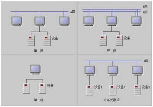
The topology supported by HMI Builder includes stand-alone, single-network, and dual-network, and can support distributed data collection, so that nodes distributed in different locations can separately collect data from different devices and share them in the entire network.
HMIBuilder Distributed Network (C/S)
The C/S (Client/Server) structure is a well-known client and server structure. It is a software system architecture, through which it can make full use of the advantages of the hardware environment at both ends, the task can be reasonably assigned to the Client and Server to reduce the communication overhead of the system. At present, most application software systems are two-tier structures in the form of Client/Server. In the C/S structure of HMI Builder, a concept of a soft bus is introduced. The SCADA layer constitutes the soft bus of the HMI Builder system. Various real-time and historical information are called and viewed through the soft bus. Various operations also pass through the soft bus. To complete, users do not feel the difference between the various nodes.
In fact, HMI Builder's C/S structure provides a peer-to-peer network structure that distributes various functions to different servers, avoiding the drawbacks of the general C/S structure that results in central host resource shortage and response bottlenecks.
HMIBuilder supports multiple topologies such as stand-alone, single-network, dual-network, and distributed data mining, as shown below:
Set up the network node
The setting of the network node is in the "System Settings\Network Settings" property page of HMIMaker. It is divided into the following types:
1. Standalone 2. Single network, you need to set the network IP address and mask.
3. For dual networks, the IP addresses and masks of A and B networks need to be set. Note that these two networks should belong to different network segments. For example, if the A network is 192.168.xx, it is better to set B network to 10.xxx.
The configuration on distributed data mining is as follows: The configuration on the network node is the same as described above. However, when setting the station parameters in HMIMaker, only the communication protocol of the I/O device to be accessed by the node is set. That is, the real-time database of several nodes in the network is different from the communication protocol of the station parameters of each node. The rest is the same.
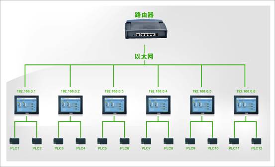
Customer's sample application of HMI Builder distributed functions:
Customer hardware connection:
6 TPC120TC-h screens; 12 Mitsubishi FX2N series PLCs;
Connect two PLCs on each screen to complete the control of the furnace and gas cabinet;
[MITSUBISHI FX2N series PLC, the selected protocol in HMI Builder is: Mitsubishi Fx2N (232, programming port) protocol;]
The parameters on each screen are:
PLC control furnace: analog quantity: 113;
State quantity: 59;
Control the PLC of the gas cabinet, the analog quantity is: 30;
There are 9 interfaces, namely: alarm, high pressure recording, pressure recording, temperature recording, display interface, ash extraction unit, coal addition unit, parameter setting, low pressure parameters;
Customer's idea: Each screen realizes the control of 12 PLCs. There are only 2 PLCs directly connected to each screen. To realize the control of the other 10 PLCs, it is only achieved through the distributed functions of HMI Builder.
The basic condition for implementation is that 6 panels are connected via a HUB in a local area network; and the name of the station and the name of each panel cannot be duplicated.
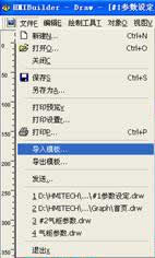
If all the interfaces and points to be controlled are placed in one project, the interface in each project is 9*6=54; the total number of points is (113+59+30)*6=1212 points; It will take a long time for the project to be completed; but don't worry, HMI Builder provides the import and export functions of station parameters and analog state quantities; and the import and export functions of the screen;
As long as the parameters and screens of the two stations on one screen are first made, the next task is to import and export the problems.
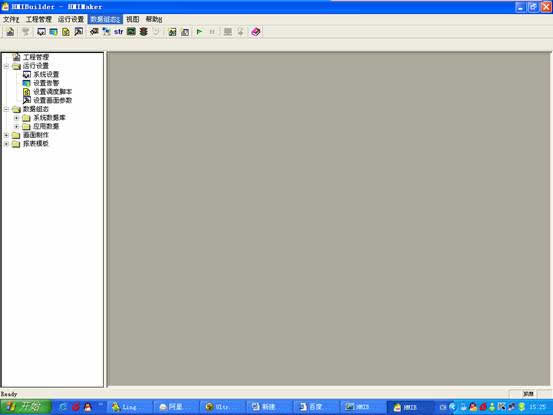
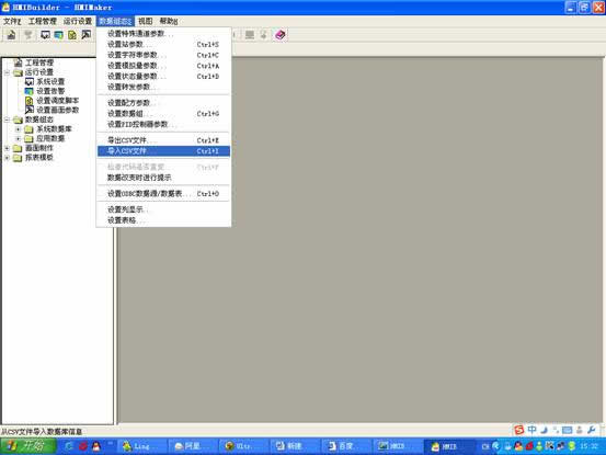
Data import and export:
In the HMIMaker interface, Data Configuration\Export CSV File
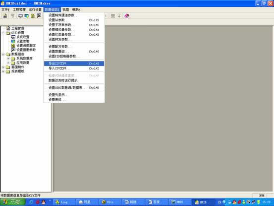
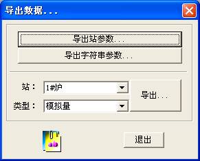
Click Export, and select the export path, and the exported file name;
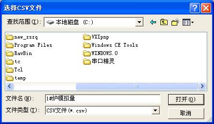
Open, there will be a prompt: export analog parameters successfully!
Click to confirm; that is, the 1# furnace has been exported;
The operation procedure is similar when importing;

Enter the established station code in the station code, sta12;
There will be a message: The import will append the analog parameters in the CSV file to the station
Click Yes. prompt:
Import analog parameters successfully!
Effective after restarting SCADA!
OK, you can;
According to this operation method, the station with the same point code is made by using the CSV import/export command.


Click OK, prompt: export template success!
OK can be;

Click OK, the import is successful;
The calculation of points;
The number of points in the HMIBuilder is only the protocol of the station, and the points are configured at the points;
That is, each screen station protocol has only the station configuration protocol directly connected to the PLC, and other stations do not need to configure the protocol.
After the project is completed, it is time to enter the distributed settings:
In the System Settings\Network Settings in the HMIMaker interface, set the SCADA network settings to Single Network, and set the corresponding A Network Address and A Network Mask;
This project: A network address: 166.166.166.115
A net mask is: 255.255.255.0
Other project configuration methods are the same;

At this point, a complex distributed engineering application is completed.