
Tag: DSP player
This article refers to the address: http://
1 Introduction
In the context of today's digital age, DSP has become a basic device in the fields of communications, computers, consumer electronics, etc., and is known as the standard bearer of the information society revolution. Ningbo University also attaches great importance to the teaching and research of DSP chip technology, but the time to open the DSP chip technology course is very short. In only two or three years, the ICETEK-VC5416-USB/PP-EDU DSP teaching experiment system was introduced at the end of 2004. . Our existing experimental content is only some confirmatory experiments. Each experimental project is limited to a single function in the experimental box, which is not targeted, and is not suitable for the characteristics of Ningbo University - short term Teaching, these problems have caused great disadvantage to the development of normal teaching work, and can not exercise students' system design ability. Therefore, it is urgent to develop experimental projects suitable for short-term teaching.
At present, the music playback system (mp3) is gradually developed from a single playback function to a combination of recording, radio, and video playback functions, and the requirements for processing chips are increasing. The DSP chip is small in size, low in power consumption, and fast in processing speed, and is very suitable for applications of new music playback systems. The members of this group have explored a set of suitable software and hardware systems for students to develop the professional courses "DSP chip technology application" and "DSP chip application system design" and the application of TMS320C54X series DSP chip. Designing the experimental program to improve students' ability to solve practical application problems, and designing and developing a music playback application system based on DSP teaching experiment box. This paper mainly introduces the design process and test results of the system.
2 system design
2.1 System Design Ideas
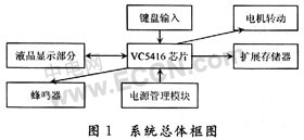
A common player has the following parts: data port, memory, microprocessor, digital signal processor, display, playback control, audio port, amplifier, power supply, etc. The display/control module of the experimental box of DSP mainly consists of the following parts: liquid crystal display, keyboard input, audio output, motor rotation and so on. The liquid crystal display portion can be used instead of the LCD display controller, and the keyboard can act as a button for the music player, the audio output is equivalent to the generation of music, and the motor rotation is a safe music playback system, and he sets the access control limit. Only enter the correct password to enter, when entering the system or exiting the system, the motor rotates in the reverse direction or in the forward direction. The system block diagram is shown in Figure 1. 2.2 System hardware design
(1) Liquid crystal part
The access and control of the LCD module is completed by the 5416 DSP on the extended I/O interface.
Control the I/O port addressing: The command controls the I/O interface address to 0x8001, the data control I/O interface address to 0x8003 and 0x8004, and the auxiliary control I/O interface address to 0x8002.
Send Control Command: The method of sending a control command to the liquid crystal display module is to write a command control word to the command control I/O interface, and then write 0 to the auxiliary control interface.
(2) Keyboard section
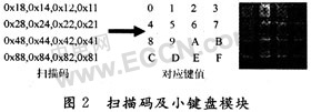
The keyboard input function mainly provides input of control signals and data. The scan code of the keyboard is given by the I/O extension address of the DSP 0x8001. When there is a keyboard input, the port is scanned to obtain the scan code. When no key is pressed, the result of reading this port is 0. The scan code of each button is arranged as shown in Figure 2.
(3) Buzzer and stepper motor part
The principle of stepper motor and buzzer is to change the high and low level of the universal output port to drive the stepping motor or buzzer according to a certain frequency. 18 McBSP pins: When the transmit and receive parts of MCBSP are in reset state, BCLKX0/1/2, BCLKR0/1/2, BDR0/1/2, BFSX0/1/2, BDX0/1/2 can be used. General purpose I/O pins, which are primarily controlled by the Pin Control Register (PCR). The operation of the general-purpose I/O is mainly to set the general-purpose serial port register, and the registers involved are the serial port control registers SPCR1, SPCR2 and the pin control register PCR.
2.2 System software design
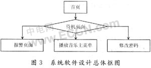
The system software design mainly includes three major functional modules: pass authentication, password modification, music playback. The core part is music playback. The overall block diagram of system software design is shown in Figure 3.
(1) Pass certification
The task that needs to be completed for pass-through authentication is to determine whether the entered pass is correct. On the passport input page, the LCD displays the current password bit. When the password is entered, a “*†symbol will be displayed. The number of passwords we set is 6 digits. The symbol of the password can be "0" on the keyboard. ~ "9", when the 6-digit password is completely entered, the "F Confirm" menu is displayed in reverse, prompting to confirm the password. If the user finds that the password is entered incorrectly, he can press the E key to re-enter the password at any time by following the prompt "E Re-enter Password" on the screen. If the user wants to abandon the request to enter the music playback system at this time, he can follow the on-screen prompt "D quit" and press D to return to the standby page. If the password is entered incorrectly three times, the system will alarm. The password enters the system correctly, and the stepper motor rotates into the music playback interface. (2) Change password
The password of the system is saved in the password variable, and the password can be modified by modifying the value of the password variable. Be sure to enter the old password before changing the password to prevent the password from being arbitrarily falsified. In the process of entering a new password, in order to ensure that the new password is the password to be set by the user, the program requires two new passwords to be entered, and the password is updated when it is confirmed that the two inputs are consistent. Return to the Set Password page if the passwords do not match.
(3) Music playback
As shown in Figure 4, after entering the music play main menu, the system will prompt the user to select the track to be played, and the user selects the play track to enter the play interface. At this time, the playback interface mainly has the following functions: music playback, music pause, playback, fast forward, exit system, and the like. After typing 0 in music playback, the music playback is paused, and the pause page is entered. After the pause, the user can select the previous song or the next song or continue to play. If the user wants to select other playback tracks, he can return to playing the main menu. Go to select the desired track to play. 3 system test results and analysis
We have completed the design and commissioning of a music playback system. The main functions are pass authentication, automatic door opening, automatic alarm, music playback and password modification. Figure 4 shows some test results of the system.
The system first displays the basic page, the information of the page can be set as needed, and then enters the welcome page (a), then the prompt page appears, the user presses the A or B button to change the password or enter the music playing system.
If you enter the music playback system, you should first enter the password to pass the verification. As shown in Figure 4(b), when the password reaches 6 digits, the F confirmation button flashes to remind the user that the password is correct and the (c) page is displayed. If the password is incorrect, enter the reset password page and alarm page (d), allowing the user to enter the password three times, otherwise the alarm will be pressed and the D key will exit the system. (e) The picture is the track selection page. The user can press the number keys (1, 2, 3, 4) to select the corresponding song to play. In the track play page (f), the user can complete the pause, playback, fast forward and exit, etc. Function, in the pause page, can also complete the functions of continuation, previous song, next song, return to the main menu and exit system, (g) is to exit the system page, and the motor rotates clockwise to close the door synchronously.
If you enter the change password page, the user first enters the old password. This is to prevent others from maliciously tampering with the password. After entering the new password twice in succession, the user is prompted to change the password successfully, and enters the system. The password modification page is shown in Figure 4(h). Shown.

3 Conclusion
We designed a music playback experiment system based on the ICETTEK-VC5416-USB/PP-EDU DSP teaching experiment box, which has the basic functions of the music playback system, namely LCD display, keyboard input, song playback, fast forward, playback. On the basis of this, we also added the system's security authentication and password modification functions to make the system more complete. The system can run stably on the experimental box, and has the advantages of simplicity, intuitiveness and safety. In addition, the system also uses multiple hardware modules and multiple DSP on-chip peripherals on the experiment box, which provides a good experimental solution for cultivating students' software and hardware system design capabilities.
Smd Resistor,Smd Chip Resistor,Thick Film Chip Resistor,Smd Resistors 10K
JINGGANGSHAN MEICHENG ELECTRONIC TRADING CO.,LTD , https://www.meicheng-tra.com