
The virtual instrument is a product of the development of computer technology and digital signal processing technology. It has the advantages of open function, flexible design, good network support, and low price. It has achieved rapid development and wide application in recent years. As a universal graphical programming language, its essence is to make full use of the latest computer technology to realize and extend the functions of traditional instruments.
The virtual instrument is designed by users themselves and defined by themselves. It combines general modules with one or more functions and calls different software modules to form different instrument functions to meet their own special needs.
In this paper, through the software design of the comprehensive parameter measurement and control system of power grid, the method and steps of LabVIEW in software design are introduced.
LabVIEW software development steps:
A. Create the front panel: Select the required controls from the control panel and place them on the front panel container according to the law.
Organize the relative position of each other, make the front panel beautiful and beautiful, and set the properties and display methods of each control.
B, create a data flow diagram: From the function panel to select the required function icons, according to the functions to be achieved, with a line to connect them in order, you can create a complete data flow diagram.
C. Perform function debugging analysis: use various methods to debug the program, modify the data flow chart until the requirements are met
1. Login settings
The login settings of the software can only be displayed after the login is successful with the sequence structure. The user login subVI property is set to start when the software is running. The login interface is popped up and the password is entered correctly into the system.
2. Menu settings
The LabVIEW window has its own custom menu function. Select “Edit - Runtime Menu†in the main menu of the VI front panel to pop up the menu editing dialog box. The user can customize the menu [1] in the dialog box as required, as shown in figure 1.2.

The menu's response program is completed by an edit configuration of the event structure. The event source of the edit event dialog is set to the menu selection (user), and the selection item is left with only the Item Tag item. Put corresponding events in the event structure, connect the item identifier with the conditional structure to select the corresponding instruction, as shown in Figure 3.
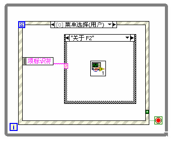
Figure 3. Menu design
In the custom menu, according to the menu items to be created, after finishing the menu customization, the corresponding SUBVI is designed for each submenu, and each subVI has its own user interface. Create a new folder and save everything you need to save during the design process.
Write a menu response program, use the menu selection node provided by LabVIEW to obtain the selected menu item, and then write a function program corresponding to the menu option in a condition structure. When the VI is running, the condition structure executes the corresponding function program according to the menu returned by the menu selection node [2]
3. Toolbar
In this software interface, buttons on the toolbar cannot be found in the LabVIEW control. This requires a custom control. Cut the corresponding icon into the drawing tool, use the cut tool to select the picture, press ctrl + c to copy it to the clipboard, if you want to do better with software like PHOTOSHOP can be modified.
Edit the control, place the OK button on the LabVIEW front panel, right-click and select "Advanced - Custom" [3], click to enter the editing state, click the button in the toolbar to make it, right click against the largest outline box , choose to import pictures from the clipboard, so that we have made the previously prepared pictures into controls.
4. Database
In the Add Users and Add Devices subVIs, you need a database. The Microsoft Access database is used here, which is a relational database that organizes databases according to a relational data model.
The LabVIEW development environment itself does not have database access capabilities. Using NI's add-on toolkit LabVIEW SQL Toolkit for database access, this toolkit is expensive and not suitable for applications. So here we use a free, multi-database, cross-platform LabVIEW database access tool LabSQL toolkit developed by the United States NI company to achieve database access
Create a new LabSQL folder in the user.lib folder of the LabVIEW installation directory and place the downloaded LabSQL in this folder. When you run it again, the LabVIEW function module will automatically load LabSQL. Between LabSQL and the database is through ODBC connection [4], the user needs to specify the data source name and driver in ODBC. Therefore, before using LabSQL again, first create a DSN in the ODBC data source in the Windows operating system. The connection between LabSQL and the database is based on the establishment of a DSN.
In the control panel of the Windows operating system, click Performance and Maintenance → Administrative Tools → Data Sources. The ODBC Data Source Manager shown in Figure 4 is displayed.
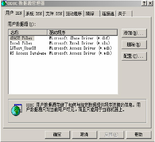
Figure 4. Data Source Manager
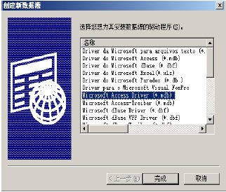
Figure 5. Create new data source
Click the "Add (D)..." button in the "System DSN" tab, and select "Microsoft Access Driver (*.mdb)" in the driver list of the "Create New Data Source" interface (Figure 5) that will pop up. , and click "Finish" button, in the subsequent dialog box (Figure 6) in the "Data Source Name (N)" column to create the name of the DSN, and click the "Select" button to select the database you need to access, Press the "OK" button to end.

Figure 6. New data source
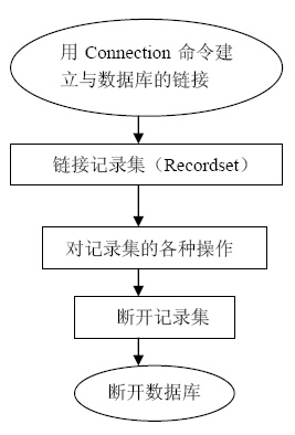
Figure 7. Database operation steps
After the above settings are completed, the database can be operated. The basic steps are shown in Figure 7.
First use ADO Connection Create.vi to create a Connection object, and then use ADOConnection Open.vi to establish a connection with the database, the database to be connected is controlled by the string ConnectionString input in the front panel controls. Use Format Into Strings on the block diagram to generate an SQL command and connect it to ADO Connection Execute.vi to execute. Create a Recordset object using ADO Recordset Creat.vi, then use the ADO Recordset Open.vi to open the Recordset object, and use the SQL query command to obtain all or part of the records in the database table. Use the function selection buttons to select controls for database operations. Use ADO RecordsetClose.vi and ADO Connection Close.vi to close the connection to the database and use ADOConnectionDestroy.vi to delete the Connection object.
In the design, click the "Add" button in the design interface to display the user registration dialog box, as shown in Figure 8.
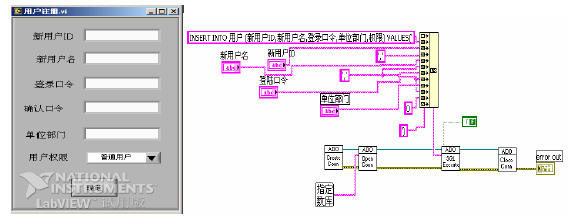
Figure 8. User registration front and back panels
In the sub-VI of the whole point data, to switch the display test image in the same interface, use the tab control to achieve this function, as shown in Figure 9
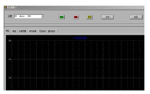
Figure 9. Whole point data
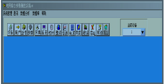
Figure 10. Interface of power grid comprehensive parameter measurement and control system
The final interface created is shown in Figure 10.
5. Conclusion
The virtual instrument soft panel is designed to provide the operator with a virtual instrument operating environment. The friendly panel is one of the important symbols of the virtual instrument design success. A virtual instrument integrated system consists of multiple virtual instruments. Each virtual instrument is controlled by a soft panel. The process of using a virtual instrument by a user is a process of operating a virtual instrument soft panel by a mouse.
In the case of hardware resources such as computers and instruments, there are different virtual instruments for different applications. Implementing some or all of the functions of the instrument through software is the core idea of ​​designing a virtual instrument. The use of object-oriented design methods, the use of visual graphic programming environment, and the establishment of a graphical user interface are the keys to instrument automation and intelligence.
references
[1] Yang Leping, et al. LABVIEW Advanced Programming [M]. Tsinghua University Press, 2003
[2] Li Haitao, et al. Customizing Windows standard window style virtual instrument panels in LABVIEW [J]. Industrial Control Computers, Vol. 2, No. 2, 2005, Vol.
[3] Zhu Xiaohua, et al. Constructing virtual instruments using ActiveX controls [J]. Computer Applications, December 1998, Vol. 18, No. 12, 21 pages.
[4] Li Gang, Lin Ling. LabVIEW—A Computer Graphical Programming Language that is Easy to Learn and Use[M]. Beijing: Beijing University of Aeronautics and Astronautics Press, 2001
Bath Mat,Shower Mat,Bathroom Mats,Bath Rugs
Cixi Mingsheng Rubber & Plastic Co.,Ltd. , https://www.popmat.com