
Today's complex FPGAs contain a number of functional blocks for implementing various circuits and systems, such as logic arrays, memory, DSP blocks, processors, phase-locked loops (PLLs) for timing generation, and delay-locked loops (DLLs), standards. I/O, high-speed digital transceivers, and parallel interfaces (PCI, DDR, etc.). These different functional blocks are usually driven by multiple clocks. FPGAs typically use an external oscillator and an internal PLL and DLL to generate the clock. System designers must decide how to combine external and internal resources to achieve the best clock tree design. The programmable clock oscillator is used as a timing reference for FPGA systems and offers a number of advantages. The primary advantage is the design flexibility of high-resolution frequency selection for clock tree optimization. Another great advantage is the spread spectrum modulation that reduces electromagnetic interference (EMI).
The intrinsically programmable silicon MEMS clock oscillator architecture can help system designers using FPGAs solve many challenges. This MEMS architecture easily integrates other features such as spread-spectrum clocks for EMI reduction, digitally controlled oscillators for jitter removal, and fail-safe features in high-speed applications.
Frequency Selection A general system requires a series of clock frequencies. Some of these are standard frequencies, which may be due to industry-enforced requirements (eg, 100MHz required by PCI Express®) or due to a wide range of applications (eg 75 MHz for SATA) Or 33.333 MHz for PCITM). These frequencies are associated with the I/O interface to ensure interoperability because the interfaces may not belong to the same system. In contrast, the user can select the clock frequency used to drive the processor, DSP, and state machine engine to optimize speed, power, or resource usage.
When speed optimization is performed, the processing engine should be driven at the highest clock frequency to maximize the number of operations per second. However, the clock period jitter must be low enough to ensure that the minimum clock period is greater than the critical timing path of the design, otherwise logic errors may occur. A common method of frequency selection is to use an internal FPGA PLL to synthesize the high frequency clock from a standard external reference oscillator. This method is only effective if the internal PLL has high frequency resolution and low jitter.
Some FPGAs integrate an internal low noise fraction PLL to meet all of these requirements. In this case, a simple external oscillator reference can be used. However, in many cases the FPGA uses a PLL with a ring VCO and an integer feedback divider to synthesize different frequencies. This PLL is small, flexible, easy to design and control, and consumes very little power. However, it is difficult to achieve both high resolution and low jitter when using such an internal PLL.
Figure 1 shows the general architecture of an integer PLL. Programming the PLL output frequency is done using a prescaler (P), a feedback divider (M), and a postscaler (N), as shown in the following equation:
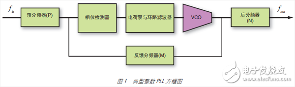
The PLL feedback loop forms a band limited control system. The output period jitter is mainly determined by the reference clock phase noise (PNin) and the internal VCO phase noise (PNVCO) as shown in the following equation:
The input reference clock phase noise and VCO phase noise are closely related to the output phase noise and are reflected by the low pass filter and the high pass filter response, respectively, such as Hin and HVCO in the expression. HVCO is directly related to the cutoff frequency of Hin. Figure 2 illustrates the relationship between Hin and HVCO in a typical second-order PLL. The highest PLL bandwidth depends on the update rate of the phase detector. The maximum actual bandwidth limit for most actual PLLs is as follows:
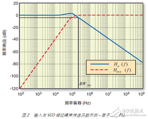
For example, if the PLL input frequency is 40MHz and P=40, the highest actual PLL bandwidth is 100kHz.
The period jitter is correlated with the phase noise by the sinusoidal filter response, as shown in Figure 4. [1] It can be seen that the period jitter is more sensitive to the overall PLL output phase noise at a frequency offset position close to fout /2. Since the PLL bandwidth is much lower than fout /2, the reference clock generally has less impact on the period jitter, while the internal VCO phase noise has a greater impact.
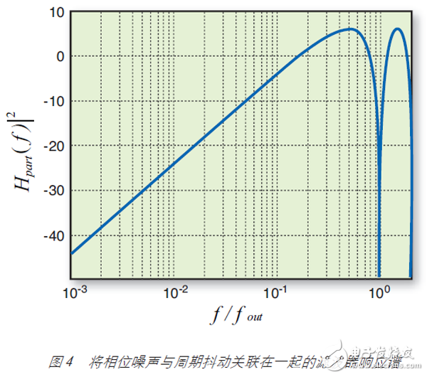
Higher PLL bandwidth reduces the impact of the internal VCO on output cycle jitter and reduces overall cycle jitter. In most cases, you can reduce internal VCO noise and improve jitter by setting a higher bandwidth. On the other hand, achieving a higher frequency resolution requires a larger divider P value, which limits the maximum PLL bandwidth. This contradiction requires a trade-off between high resolution and low jitter. The use of an external high-resolution oscillator can alleviate this problem because high resolution can be achieved by external reference.
The Anti-explosion Screen Protector is a Screen Protector that can effectively buffer impact, prevent the screen from bursting, or prevent the glass panel from breaking and falling apart due to accidental impact of the mobile phone. It has gloss, texture and surface hardness. The Explosion-proof Screen Protector strengthens the screen and reduces the chance of cracking, broken tempered glass is no longer frequently replaced.
Compared with other Screen Protectors, Explosion-proof Screen Protectors have the following advantages:
1. Anti-shattering: The PET material of the Explosion-proof Screen Protective Film has high strength, flexibility and elasticity, can fully decompose the impact force, and can effectively prevent the screen from being broken or damaged when the screen is impacted or dropped by external forces.
2. HD Clear: The Explosion-proof Screen Protector is made of high-quality PET material, which can maintain a high-definition screen display effect and truly display the original screen color.
3. Anti-fingerprint: The Anti-explosion Screen Protector has a built-in oleophobic and waterproof coating to prevent fingerprints and stains on the phone screen, providing your phone with original texture and perfect touch screen response speed.
The use of an Explosion-proof Anti-explosion Screen Protector can effectively enhance the durability and protection of the mobile phone screen, reduce the risk of screen cracking and damage, and at the same time protect the clarity and quality of the screen display. Ideal for protecting your screen.
PET Screen Protector, Explosion-proof Screen Protector, Explosion-proof Screen Protective Film, Explosion-proof Protective Film,Anti-explosion Screen Protector
Shenzhen Jianjiantong Technology Co., Ltd. , https://www.jjtbackskin.com