
The importance of finding "perfect" FPGAs for design is escalating, with power consumption becoming a major consideration. Power management is critical in most applications. Some standards have set a power cap for a single card or a single system. Because of this, designers must consider power consumption issues earlier in the design process, generally starting with the choice of FPGA.
Reducing the power consumption of the FPGA simplifies board design by reducing supply voltage, simplifying power supply design and thermal management, and reducing power distribution surface requirements. Low power consumption also extends battery life and increases system reliability (systems with lower operating temperatures last longer).
The power challenge is accompanied by the advent of every generation of process technology, and the size of transistors can be reduced according to Moore's Law. However, this phenomenon also has the side effect that the leakage current in each transistor increases, which leads to an increase in static power consumption (the total current consumed by the FPGA increases in an inactive state). An increase in FPGA performance increases the clock rate and increases dynamic power consumption. Static power is caused by transistor leakage current, and dynamic power is dependent on the switching frequency of the programmable logic and I/O. As the capacity of each generation of FPGAs increases, both types of power consumption continue to increase. Higher logic capacity means more leakage current per device and more transistors operating at higher speeds.
Given these issues, designers must have a clearer understanding of power and thermal management issues early in the design process. Adding a heat sink to the device is not enough to solve these problems. Designers must therefore minimize the amount of logic used in the design.
First look at a few guidelines to help understand what steps should be taken at various stages of the design process to reduce the power consumption of the FPGA. Obviously, thoroughly understanding these issues early in the design process can bring the greatest benefits.
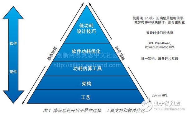
Figure 1 illustrates the different design points throughout the design process, including FPGA selection and low-power design techniques.
7 Series Process Technology Care should be taken in the selection of FPGAs to help the user determine the leakage current and performance of the device. The Xilinx 7 Series FPGAs feature a 28 HPL (28nm high performance, low power) process that delivers significant performance while reducing power consumption (see the cover story of the 41st issue of Xilinx China Newsletter). Choosing devices fabricated with the low leakage current HPL process avoids the use of complex and costly static power management schemes in FPGA designs.
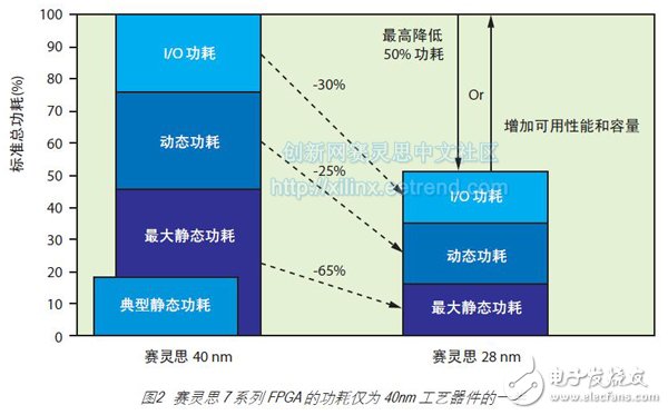
Although the performance of the 28 HP process FPGA does not exceed the performance of other FPGAs in the 7 series, its static power consumption is less than half of the static power consumption of competitor FPGAs, and it does not cause serious leakage current problems. Figure 2 shows the overall reduction in the Series 7 products, which is half the total power consumption of previous generation 40nm FPGA devices.
Designers can choose larger FPGAs during the development phase and then choose smaller FPGAs during the production process. Choosing a smaller FPGA not only reduces costs but also reduces system power consumption.
All 7 Series FPGAs have a unified architecture. This unified architecture facilitates easy up or down migration between different FPGA devices in the Xilinx 7 Series. If you need to migrate from a Virtex®-6 or Spartan®-6 device to a 7 series device or migrate between 7 series devices, please refer to the “7 Series User Guide†(UG429).
Xilinx Stacked Silicon Interconnect Technology For larger systems, designers typically choose multiple FPGAs. This architecture often requires high-speed data transfer between FPGAs, which is a complex and difficult task. This problem can be avoided by choosing large 7-series FPGAs fabricated using Xilinx stacked silicon interconnect technology, such as the XC7V1500T and XC7V2000T devices. Simply put, stacked silicon interconnect technology is to place multiple chips in a plug-in structure with thousands of connections to create a unified large device. One of the advantages of stacked silicon interconnect technology is that it can significantly reduce static power consumption compared to similarly sized devices using standard monolithic circuits.
Stacked Silicon Interconnect Technology (SSI) also significantly reduces I/O interconnect power consumption. Compared to the method of arranging multiple FPGAs on a board, SSI technology has a great advantage, and its I/O interconnect power consumption is 100 times lower than the equivalent interface built with I/O and transceiver (bandwidth/W). . The power consumption is drastically reduced because all connections are built on the chip and no signal is required to drive the signal off-chip, which enables incredibly high speed and low power consumption.
Voltage Expansion Enhancement Options Xilinx 7 Series FPGAs offer important voltage expansion options.
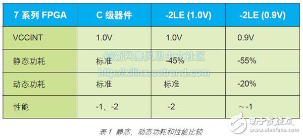
The 7 Series FPGAs offer an extended (E) temperature range (0-100 degrees Celsius) for -3L and -2L devices. Due to the margin provided by the 28 HPL process, the -2LE device can operate at 1v or 0.9v. These devices are named -2L (1.0V) and -2L (0.9V), respectively. The speed performance of a -2L device operating at 1.0V is comparable to that of the -2I and -2C devices, but the static power consumption is significantly reduced. The performance of the -2L device operating at 0.9V is similar to that of the -1I and -1C devices, but both static and dynamic power consumption are degraded.
Simply reducing the voltage of these devices to 0.9V reduces the static power consumption by approximately 30%. Lowering the voltage also reduces performance, but Xilinx screens these -2L (0.9V) devices based on speed and tighter leakage current specifications. This screening method enables the device to consume 55% less power than the standard speed grade device under worst-case conditions.
By choosing a -2L device, users can further reduce dynamic power consumption. Since dynamic power is proportional to VCCINT2, a 10% reduction in VCCINT can result in a 20% reduction in power consumption.
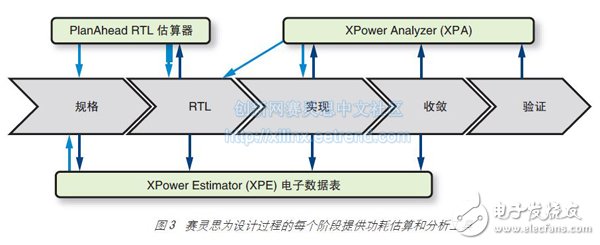
Power Estimation Tools Today's marketplace has a wealth of tools for designers to choose from to evaluate the thermal and power requirements of the FPGA design throughout the development process. Figure 3 shows the Xilinx tools available at each stage of the FPGA development process.
To reduce power consumption, users must do everything possible to reduce the amount of logic used in the design. The first is to use a dedicated hardware module instead of implementing the same logic in the CLB.
At the beginning of the design, the XPower EsTImator (XPE) spreadsheet enables early estimation of power consumption prior to initial design and implementation. XPE can be used for architectural evaluation and device selection to help determine the appropriate power and thermal management components needed for your application.
PlanAheadTM software is used to estimate the distribution of design power at the RTL level. Designers can use constraints or GUIs to set the device's operating environment, I/O properties, and default activity. The PlanAhead software then reads the HDL code, estimates the required design resources, and performs a statistical analysis of the operational status of each resource to arrive at a power estimation report. Because of the more detailed information about the design intent, the RTL power estimator is better than the XPE spreadsheet, but less accurate than the XPower Analyzer's post-layout analysis.
Xpower Analyzer (XPA) is a tool designed to analyze the power consumption of place and route designs. It features a comprehensive, comprehensive GUI that provides detailed analysis of power and heat generation information for specific operating conditions.
Users can switch between two different views to confirm the power consumption or design level power consumption of various types of modules (hard tree or DSP modules such as clock trees, logic, signals, IO modules, BRAM, etc.). Both views allow the user to perform detailed power analysis. It also provides a very efficient way to determine the most power-hungry modules or components in your design, simplifying power optimization.
ZGAR bar 2000 Puffs
ZGAR electronic cigarette uses high-tech R&D, food grade disposable pod device and high-quality raw material. All package designs are Original IP. Our designer team is from Hong Kong. We have very high requirements for product quality, flavors taste and packaging design. The E-liquid is imported, materials are food grade, and assembly plant is medical-grade dust-free workshops.
Our products include disposable e-cigarettes, rechargeable e-cigarettes, rechargreable disposable vape pen, and various of flavors of cigarette cartridges. From 600puffs to 5000puffs, ZGAR bar Disposable offer high-tech R&D, E-cigarette improves battery capacity, We offer various of flavors and support customization. And printing designs can be customized. We have our own professional team and competitive quotations for any OEM or ODM works.
We supply OEM rechargeable disposable vape pen,OEM disposable electronic cigarette,ODM disposable vape pen,ODM disposable electronic cigarette,OEM/ODM vape pen e-cigarette,OEM/ODM atomizer device.

ZGAR bar 2000 Puffs Disposable Vape, bar 2000puffs,ZGAR bar 2000 Puffs disposable,ZGAR bar 2000 Puffs,ZGAR bar 2000 Puffs OEM/ODM disposable vape pen atomizer Device E-cig
ZGAR INTERNATIONAL(HK)CO., LIMITED , https://www.szvape-pods.com