
The A/D converter is used to convert analog quantities into digital quantities through a certain circuit. The analog quantity can be an electrical signal such as voltage or current, or a non-electrical signal such as pressure, temperature, humidity, displacement, and sound. However, before the A/D conversion, the input signal input to the A/D converter must be converted into a voltage signal by various sensors through various sensors. After A/D conversion, the output digital signal can have 8 bits, 10 bits, 12 bits, 14 bits, and 16 bits.
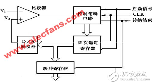
Ad conversion work principle successive approximationSuccessive approximation A/D is a relatively common A/D conversion circuit with a conversion time of microseconds. The A/D converter using the successive approximation method is composed of a comparator, a D/A converter, a buffer register and a control logic circuit as shown in the figure. The basic principle is to compare and test from the high position to the low position. It seems that the object is called by the balance, and the weight is increased or decreased from heavy to light. The successive approximation conversion process is: when the initialization is started, the successive approximation register bits are cleared; when the conversion starts, the highest position of the register is successively approximated to the D/A converter, and the analog quantity generated by the D/A conversion is sent. The comparator, called Vo, is compared to the analog Vi to be converted to the comparator. If Vo "Vi, this bit 1 is reserved, otherwise it is cleared. Then, the next high order bit of the successive approximation register is set to 1, and the new digital quantity in the register is sent to the D/A converter, and the output Vo is compared with Vi. If Vo "Vi, the bit 1 is reserved, otherwise it is cleared. Repeat this process until the lowest bit of the register is approached. After the conversion is completed, the digital quantity in the successive approximation register is sent to the buffer register to obtain a digital output. The successive approximation operation is performed under the control of a control circuit.
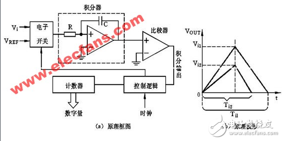
The A/D converter using the double integration method consists of electronic switches, integrators, comparators, and control logic. As shown below. The basic principle is to convert the input voltage into a time interval proportional to its average value, and then convert this time interval into a digital quantity, which is an indirect conversion. The process of double-integration A/D conversion is: first switch the switch to the analog quantity Vi to be converted, Vi sample is input to the integrator, and the integrator performs the positive integration of the fixed time T from zero. After the time T is reached, the switch Then turn on the reference voltage VREF opposite to the polarity of Vi, input VREF to the integrator, and perform reverse integration until the output is 0V to stop the integration. The larger Vi, the larger the integrator output voltage and the longer the reverse integration time. The value counted by the counter in the reverse integration time is the digital quantity corresponding to the input analog voltage Vi, and the A/D conversion is realized.
The A/D converter using voltage-frequency conversion method consists of a counter, a control gate, and a clock gate control signal with a constant time, as shown in the following figure.
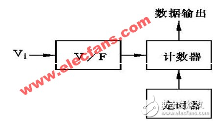
Its working principle is that the V/F conversion circuit converts the input analog voltage into a pulse signal proportional to the analog voltage.
The working process of the voltage frequency conversion method is: when the analog voltage Vi is applied to the input end of the V/F, a pulse whose frequency F is proportional to Vi is generated, and the pulse signal is counted in a certain time, and the time is up. The count value of the counter is proportional to the input voltage Vi, thereby completing the A/D conversion.
Pic microcontroller ad conversion c program#include《pic.h》
#define uchar unsigned char
#define uint unsigned int
__CONFIG(0x3FB1);
Void init();
Void Delay();
Unsigned int getad();
Void Display(unsigned char a,unsigned char b,unsigned char c);
Unsigned char DIG_CODE[17]={
0x3f, 0x06, 0x5b, 0x4f, 0x66, 0x6d, 0x7d, 0x07,
0x7f, 0x6f, 0x77, 0x7c, 0x39, 0x5e, 0x79, 0x71};
Display codes of //0, 1, 2, 3, 4, 5, 6, 7, 8, 9, A, b, C, d, E, F
Void main()
{
Unsigned int led;
Unsigned char a ,b,c;
Init();
While(1)
{
Led = getad();
a = led/100;
b=led%100/10;
c=led%10;
Display(a,b,c);
}
}
Void Display(unsigned char a,unsigned char b,unsigned char c)
{
PORTB=DIG_CODE[c];
RC4=1; RC5=0; RC6=0;
Delay();
PORTB=DIG_CODE[b];
RC4=0; RC5=1; RC6=0;
Delay();
PORTB=DIG_CODE[a];
RC4=1; RC5=1; RC6=0;
Delay();
}
Unsigned int getad()
{
Unsigned int ad8;
ADGO =1;
While(ADGO);
Ad8 = ADRES;
Return(ad8);
}
Void init()
{
TRISA =1;
TRISB = 0; //portB output
TRISC = 0;
ADCON0 = 0x41;
ADCON1 = 0x00;
Delay();
}
Void Delay()
{
Unsigned char a,b,c;
For(c=1;c》0;c--)
For(b=10;b》0;b--)
For(a=5;a)0;a--);
}
Dp To Hdmi Connector,Dp Monitor Connector,Dp Connector Monitor,Display Port To Hdmi Connector
Dongguan Tuojun Electronic Technology Co., Ltd , https://www.fibercablessupplier.com