
Microdischarge is a phenomenon of radio frequency breakdown that occurs inside a microwave device under vacuum conditions. In recent years, with the development of space technology, the power of microwave components is getting larger and larger, which makes the possibility of micro-discharge in space greatly increased. Microwave devices operating in high-power states, micro-discharge effects occur when power, RF, and internal structural dimensions of the device meet a certain relationship. This phenomenon depends on factors such as vacuum pressure, processing technology, surface treatment, materials, and pollution. . Once the micro-discharge is generated, it will cause serious consequences, resulting in an increase in the standing wave ratio of the microwave transmission system, an increase in the reflected power, and an increase in the noise level, resulting in the system not working properly. High-level micro-discharge can cause breakdown, total RF power reflection, permanent damage to components, and loss of communication channel capability. The occurrence of micro-discharge will have a serious impact, and the mechanism of micro-discharge is complicated, and it has not yet been fully grasped. At the same time, the actual manufacturing process and process defects, as well as possible contamination during storage, may lead to the actual micro-discharge threshold. It is lower than the design; therefore, the microdischarge test must be performed on the fabricated device and the device to be used.
1 micro-discharge phenomenon and detection principleThe micro-discharge effect is caused by the secondary electron emission on the surface of the device. As can be seen from Fig. 1, an avalanche phenomenon occurs, which is resonant because the electron transit time must be an odd multiple of half of the RF field period. This resonance effect is dependent on factors such as the RF field, device structure gaps, and surface secondary electron emission characteristics. Therefore, in the vacuum case, when the average free path of electrons is larger than the gap size of the device structure; the gap size and harmonic frequency in the microwave device make the electron transit time an odd multiple of half of the RF field period; the surface secondary electron emission coefficient is greater than 1 Then, the electrons generate electron secondary doubling under the acceleration of the strong micro-discharge field, that is, the micro-discharge phenomenon. The surface secondary electron emission characteristics are related to materials, surface treatment, pollution, temperature, speed at which the electrons strike the board, and gap voltage.
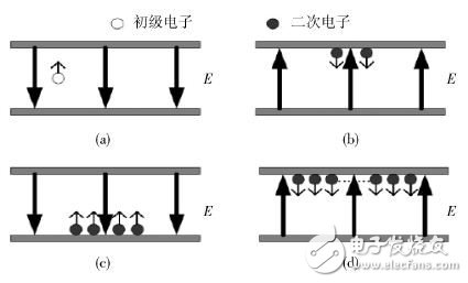
Fig.1 Schematic diagram of the process of microdischarge on bimetal surface
The generation of micro-discharge is strongly dependent on the electronic secondary emission characteristics of the device surface. Although the device meets the micro-discharge design tolerance requirements during product qualification, the micro-discharge effect test is still required for the newly processed positive product. Factors such as contamination, surface material conditions, binders and lubricants that are not anticipated during product processing; increased edge field strength and other factors can cause the product micro-discharge effect threshold to decrease, so the flight device itself or flight sample must be Tested and left with power headroom (typically designed to be 3~6 dB).
According to the occurrence of micro-discharge, it will have certain influence on the input and output signals of the device under test, such as changing the phase and amplitude of the input signal, generating harmonic changes of the input signal, or increasing the reflected power of the device under test. At the same time, the occurrence of the micro-discharge also generates a discharge of gas or ions from the surface of the device to be tested, or a current generated by the discharge. Micro-discharge detection is based on these two characteristics to determine whether the device under test has a micro-discharge.
At present, various methods for detecting micro-discharge have been studied at home and abroad, but due to the complexity of the micro-discharge phenomenon, various detection methods need to be discussed in terms of detection sensitivity and judgment of discharge reliability. For example, discharge may occur during detection. However, because the device system of the detection method has a certain delay, the discharge cannot be judged in time, or other phenomena are similar to the discharge, and thus it is mistakenly judged as discharge.
The composition and characteristics of the general microdischarge detection system are described below. The micro-discharge detection system mainly includes four parts: a power loading system, a vacuum tank, a high-power absorption system, and a detection system. The power loading system produces the required test signal that is placed in the device under test in the vacuum system and a portion of the output power is absorbed by the load. The detection system is coupled at both ends of the vacuum tank to detect the phase change of the phase, amplitude and noise of the test signal at both ends of the test object in the vacuum system, thereby determining whether the device under test has been discharged; or installing in the vacuum system An electronic probe or fiber is connected to the display device to detect if a discharge has occurred. The basic schematic diagram of the micro-discharge detection system is shown in Figure 2 (where * is an electron probe or fiber). Detailed testing methods are described below.
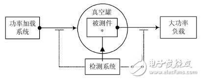
(In the figure, * is the electronic probe or optical fiber that penetrates the DUT.) Figure 2 Basic block diagram of the micro-discharge detection system
2 Introduction to testing methodsThe micro-discharge detection method is divided into a local method and a global method, such as an electron probe or a photomultiplier tube/fiber in FIG. The local method has photoelectric multiplication detection and electron probe detection; the global detection method has second harmonic detection, residual substance detection, forward and backward power zero detection, near carrier noise detection and amplitude modulation method. The micro-discharge local detection method uses the discharge to increase the electron concentration or excite the gas discharge; the global detection method utilizes the change characteristics of the signal during the micro-discharge process, and detects the micro-discharge by observing the change of the signal before and after.
The standards for microdischarge design and testing specified by the European Space Standards Coordination Organization clearly state that two methods must be included in the microdischarge test, one of which must be a global test. Therefore, the research on the detection method of micro-discharge cannot be ignored.
2.1 Local detection method
2.1.1 Photomultiplier detection method
Photomultiplier detection is a very effective method for detecting microdischarge. It detects the discharge using a photograph taken by an electron secondary multiplying device that can ionize the participating gas molecules from the surface of the electron secondary multiplying material or present in the vacuum system. Place the fiber through an aperture in the interior of the RF component and as close as possible to the discharge area. Connect the other end of the fiber to the photomultiplier outside the vacuum can. Any output on the photomultiplier may be Displayed on the oscilloscope and triggers an electronic quadratic multiplication event detector.
This detection method can accurately determine the discharge for the micro-discharge detection, but it is necessary to accurately determine the discharge position in advance, and also needs to punch holes in the device. This can only be measured for the test piece, but it will affect other performance of the device, so it is not A method commonly used in laboratories to detect microdischarges.
2.1.2 Electron probe detection method
The electron probe detection method detects the microdischarge phenomenon by detecting a change in the electron concentration using a probe mounted in the device to be tested. The occurrence of microdischarge is always accompanied by the generation of a large number of free electrons. The concentration of electrons in the microwave device can be measured by inserting a positively charged probe in the region where the microdischarge is expected to occur. The negatively charged electron probe is adsorbed by the probe. Thus, a small but detectable current is generated in the probe, and the value of the current can be used to indicate the electron concentration.
This method of detection is very easy to implement and is therefore a popular choice in many tests. However, this detection method also has some disadvantages, such as the need for a circuit to amplify the weak current, so that the detection speed is slow, and is mainly used as an auxiliary detection in use; at the same time, this is not always true for discharge including surface discharge mechanism. It is a suitable detection method; finally, as with the photomultiplier detection method, it is necessary to pre-design holes on the device to be tested, thereby causing limitations of the micro-discharge test.
2.2 Global detection method
2.2.1 Residual substance testing
The residual matter detection method uses a mass spectrometer to detect contaminants released in the electron secondary dynode device and moisture present. Due to the use of aluminum or coated components, the surface of the material absorbs moisture during processing, and is released during electron secondary doubling discharge. When the electron secondary doubling discharge is released, it contains glue and ring. Those synthetic elements of oxyresin and other non-metallic compounds will liberate hydrocarbon gases. The mass spectrometer is loaded as part of the vacuum system through the inlet of the vacuum tank, and a vacuum valve is used to isolate the light and dark rustic heads, thus preventing unnecessary contamination during normal operation and with particularly dirty components.
The detection method has a slow detection speed, and cannot detect the rapid micro-discharge moment, and the micro-discharge occurs and the detection of the device has a certain delay.
2.2.2 Near-Carrier Noise Detection
Micro-discharge is a resonance phenomenon and increases the noise of the frequency near the carrier. If the method can be used to filter out the carrier, the improvement of the noise level in the frequency band near the carrier can be detected by the spectrum analyzer. If this type of detection device is used in combination with a low noise amplifier, it is a very sensitive detection method.
This method can be used for single-carrier or multi-carrier signals, but it is not suitable for operation in pulse mode because the pulses generate harmonics. If the pulse length and form are not properly selected, the pulses will generate harmonics in the test band. Another problem with this approach is that other phenomena that cause noise can be mistaken for microdischarges, such as loose joints in the test system, which can cause noise similar to microdischarge.
2.2.3 Harmonic detection method
Harmonic detection is one of the most reliable methods of detection used. It uses the micro-discharge to generate harmonic components of the input signal to detect the discharge phenomenon. Harmonic detection method is used. In order to optimize the operation, it is necessary to filter out the harmonic components generated by the high-power amplifier and the nonlinearity of the signal source itself at the input front end. It is also necessary to couple the micro-discharge nonlinear effect well at the output end, that is, signal generation. Harmonic component.
This detection method has several advantages: the detection system is easy to set up, the detection discharge is very fast and reliable, and it is very useful to use the harmonic detection method especially in the case where the multi-carrier micro-discharge occurs very shortly. However, this detection method is similar to the near-carrier noise detection. It may happen that the harmonic component generated by non-micro-discharge is mistaken for the discharge phenomenon. Therefore, it should be used in conjunction with other detection methods (excluding the near-carrier noise detection method). Get up and judge the discharge. In practical applications, as the frequency of use increases, more stringent requirements are imposed on the detection device, which imposes conditional restrictions on use.
2.2.4 Forward and backward power detection
The forward and backward power detection method detects the discharge phenomenon by observing the reflected power and the input power of the device under test with a power meter. Mismatch in different microwave component connections results in reflected power. In a well-designed system, the reflected power is small when the matching connections between different components are well designed, while the high Q devices are only at a specific frequency. (or a few specific frequencies) is well matched. If the discharge electron resonance phenomenon occurs, the device will be detuned and the matching ability will be reduced, resulting in an increase in the reflected power, which will serve as the basis for the discharge judgment.
This detection method is very sensitive and reliable in general, because there is almost no other situation causing mismatch, which is misjudged as discharge; and it works well in pulse mode because there is no need to observe the spectrum of the signal. However, for poorly matched devices and low Q devices, this detection method is not sensitive enough.
2.2.5 Forward and backward power zero detection method
The forward-back power zero detection method is established by using the change of signal amplitude and phase during the micro-discharge process, and is the most sensitive micro-discharge detection method in the current application. It uses a bridge coupler to attenuate the amplitude of the reflected power from the device under test and a part of the signal passing through the device to achieve a zero-amplitude state. As long as the forward and reverse power changes, it will cause a zero-state change, which is considered to be a discharge.
This detection method is very sensitive, because as long as the forward and reverse powers change a little, the zeroing level changes to determine the microdischarge; and the zeroing detection method works well in the pulse mode. However, this kind of detection method may also be misjudged under certain circumstances. For example, the looseness of the joint in the test system, the impurity of the device under test, or the sloshing of the waveguide system during the test may cause a slight change in the reflected power, which may be mistaken. It is judged as discharge.
2.2.6 amplitude modulation method
The amplitude modulation method is to modulate a small modulated low frequency signal amplitude to the RF signal to the test link at the input front end. Since the amplitude modulation depth is low, before the micro discharge occurs, the spectrum only has the carrier signal and the sideband signal, and the remaining components are almost submerged in the noise. in. In micro-discharge, the signal energy is shifted from the carrier and the amplitude-modulated side-frequency signal to the near-carrier noise. Due to the nonlinear action of the micro-discharge, the harmonic of the side-frequency signal is generated, and the carrier energy is modulated on the surrounding noise due to the change of the carrier energy. The harmonics of the sideband signal increase at a higher amplitude. From the changed spectrum, the sideband signal and its harmonic changes can be clearly observed, and the microdischarge effect is detected based on such dramatic changes.
This detection method is simple in equipment and relatively sensitive to detection, especially when it is close to the micro-discharge threshold, so it is suitable for detecting weak discharge phenomena. However, this detection method detects that the discharge is detected by the change of the side frequency component of the near carrier, so that it is not suitable to detect the discharge in the multi-carrier and pulse modes. At the same time, this method is only a theoretical study, and there are relatively few engineering tests. Therefore, further research is needed.
3 Summary analysis of micro-discharge detection methodsAt present, there are many methods for micro-discharge detection in engineering, but no one detection method can detect the micro-discharge phenomenon sensitively and reliably at the same time. As a whole, the local detection method can accurately detect the discharge position, but this It is based on a predetermined position that is prone to discharge, and the local detection method also needs to punch holes in the device to be tested, which is not feasible for the flight device test; the global detection method can detect whether the device under test is discharged, This can be met by testing in a general test. Furthermore, as described above, various methods have advantages and disadvantages. When performing micro-discharge detection, it is necessary to consider the characteristics of the device to be tested, the detection equipment, etc., and comprehensively select the detection method. Finally, it can be seen from the analysis of various detection methods that none of the detection methods is absolutely reliable. Therefore, at least two detection methods are required when performing the micro-discharge test, and each detection method needs to be selected when selecting the detection method. The principle of comprehensive selection of complementary detection methods for micro-discharge test, such as engineering often used forward and backward power detection method and harmonic detection method or forward and backward power zero detection together to determine the discharge phenomenon.
In view of the above analysis, research on microdischarge detection methods remains to be explored. Combined with the study of microdischarge theory, it is necessary to study the microdischarge detection method. Especially with the development of aerospace technology, the frequency of use of high-power devices is increasing, the micro-discharge test requires the use of pulse mode, and the micro-discharge detection method currently available in pulse mode is limited, therefore, the micro-discharge detection method for pulse mode The research is even more urgent.
10.1 Inch Laptop,win10 Laptops,win11 Laptops
Jingjiang Gisen Technology Co.,Ltd , https://www.gisentech.com