
In some systems, PID control is required, such as some board acquisition systems. Even in some DCS and PLC systems, the PID control loop of the system is sometimes expanded. Due to the limitation of system hardware and loop, PID control needs to be added to the computer. Loop. In the Zijinqiao system, the real-time database provides the PID control point to meet the needs of PID control.
Enter the real-time database configuration and select the PID control point when creating a new point. The PID control provided by Zijinqiao can provide various control methods such as ideal differential, differential advance, and actual differential.
When PID control is performed, the PV of the PID can be connected to the actual measured value, and the OP is connected to the actual output value of the PID. In this way, when the real-time database is running, it can be automatically PID controlled.
Adjustment of PID parameters:
It is of course the most ideal method to determine the PID parameters in a PID method if the PID parameters are tuned. However, in practical applications, the parameters of the PID are determined by the trial method.
Increasing the proportionality factor P will generally speed up the response of the system. In the case of static difference, it will help to reduce the static difference. However, the excessive proportional coefficient will make the system have a large overshoot and generate oscillation, which will make the stability change. Bad.
Increasing the integration time I is beneficial to reduce overshoot, reduce oscillation, and increase the stability of the system, but the system static elimination time becomes longer.
Increasing the differential time D is beneficial to speed up the response speed of the system, reduce the system overshoot and increase the stability, but the system's ability to suppress the disturbance is weakened.
In the test, you can refer to the influence of the above parameters on the system control process, and implement the first step, the post-integration, and then the differential setting step for the parameter adjustment.
First, set the proportion part. The proportional parameter is changed from small to large, and the corresponding system response is observed until a response curve with fast response and small overshoot is obtained. If the system does not have a static difference or the static difference is already within the allowable range and the response curve is satisfactory, then only the proportional regulator is required.
If the static difference of the system cannot meet the design requirements based on the proportional adjustment, the integral link must be added. Set the integration time to a relatively large value at the time of the whole timing, and then slightly reduce the adjusted proportional coefficient (generally reduced to 0.8 of the original value), and then reduce the integration time, so that the system maintains good dynamic performance. In the case, the static difference is eliminated. In this process, the proportional coefficient and the integration time can be repeatedly changed according to the response curve of the system, in order to obtain a satisfactory control process and tuning parameters.
If the repeated adjustment of the dynamic process of the system in the above adjustment process can not obtain satisfactory results, the differential link can be added. First, the differential time D is set to 0, and the differential time is gradually increased on the basis of the above, and the proportional coefficient and the integration time are changed accordingly, and the test is gradually completed until a satisfactory adjustment effect is obtained.
PID control loop operation:
When the PID control loop is put into operation, it can first be set in the manual state. At this time, the set value will automatically track the measured value. When the system reaches a relatively stable state, it can be switched to the automatic state. Avoid system instability and system instability.
Control of complex loops:
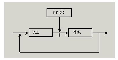
Feedforward control system:
In the usual feedback control system, the disturbance has certain consequences, and the feedback can be generated to suppress the interference, thus causing the adverse consequences of the hysteresis control. In order to overcome this kind of poor control of hysteresis, after receiving the interference signal by the computer, insert a feedforward control function to completely cancel the influence of the interference on the control variable just before the interference point, so it is named Disturbance compensation control.
In the control system of Zijinqiao, the result of the feedforward control calculation can be used as the output compensation amount OCV of the PID control, and the compensation is added, thus forming a feedforward control system.
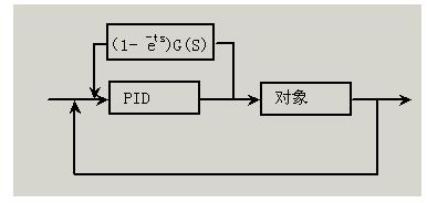
Pure delay compensation control:
In the actual control process, due to the delay of the actuator and the measuring device, the system may be a purely lagging process, such as the temperature control, the delay time may be more than 10 minutes. This hysteresis nature often causes overshoot or oscillation of the controlled object, making it difficult for the system to reach a stable process. Therefore, a compensation link can be connected in parallel during the control process to compensate for the hysteresis in the controlled object, which allows the system to quickly reach the stabilization process.
The pure hysteresis control system uses the result of the lag compensation as the input compensation amount ICV of the PID controller and as the input compensation offset compensation. This constitutes a purely delayed SMITH predictive control loop.
FGI`s FGSVG series Static Var Generator (SVG) adopts modern power electronics, automation, microelectronics and network communication technologies, adopts advanced instantaneous reactive power theory and power decoupling algorithm based on synchronous coordinate transformation, operate as the control target with the set reactive power and size, power factor and grid voltage, etc. FGI`s static generator for sale meets the high-end needs of customers with its easy operation, high performance and high reliability.
Static Var Generator
Static Var Generator,Svc And Statcom,Statcom In Power System,Statcom Systems,Static Var,Active Var
FGI SCIENCE AND TECHNOLOGY CO., LTD , https://www.fgi-tech.com