
Controller Area Network (CAN) is a serial data communication protocol developed by BOSCH in Germany to solve the data exchange between many electronic devices in modern automobiles. It has high reliability and good error detection capability. There are two types of CAN buses: high-speed (500 kb/s) and low-speed (125 kb/s). These two buses are connected through a gateway to share data between two LANs.
At present, with the increasing requirements for the complexity and refinement of the system, the traditional centralized control is increasingly unable to meet the requirements in real-time and reliability, and the distributed control has been widely used. Distributed control means that the system consists of a main controller and a number of sub-controllers. The sub-controllers process a part of the system functions to interact with the main controller in parallel or serially.
1 overall design of the system
This design mainly completes the smart car driving on the pre-paved road. The block diagram of the whole system hardware is shown in Figure 1. It includes the acquisition node and the control node, and the data interaction between them is done through the CAN bus. The acquisition node collects road information through the sensor and transmits it to the microcontroller through the signal conditioning circuit. The microcontroller processes the information and sends the data to the CAN bus. The control node reads the data on the bus and converts it into control commands, controlling the actuator to ensure that the smart car does not deviate from the road and maintains a high speed. 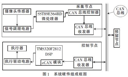
2 node hardware interface design
This article refers to the address: http://
2.1 Acquisition node SST89E564RD and CAN bus interface
The SST89E564RD does not have a CAN module itself, so the CAN bus controller is extended and connected to the bus via the CAN bus transceiver. The CAN controller used in this design is SJA1000, which is compatible with CAN2.0B protocol, and is initialized by single-chip microcomputer, which mainly realizes communication tasks such as data receiving and sending. The transceiver uses PCA82C250, which is an interface chip between a widely used CAN controller and a physical bus, which can differentially transmit and receive information on the bus. In order to further improve the anti-interference ability of the system, high-speed optocoupler 6N137 is used to isolate between PCA82C250 and SJA1000 to reduce crosstalk caused by high common-mode voltage of different nodes and even damage to the device, improve system reliability, and communicate The rate is up to 10 Mb/s, which fully meets the needs of the CAN bus. The hardware interface of SST89E564RD and CAN bus is shown as in Fig. 2. 
2.2 Control node DSP and CAN bus interface
The TMS320F2812 DSP chip integrates a complete enhanced CAN controller, called eCAN. In the hardware design, there is no need to add a separate CAN controller to implement the underlying protocol of the CAN bus, and directly connect to the bus through the transceiver PCA82C250. The interface between DSP and CAN bus is shown in Figure 3. 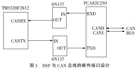
3 CAN node software design
3.1 CAN bus communication data format
The CAN protocol communication format includes four types of frame formats: data frame, remote frame, error frame, and overload frame. Among them, the transmission of data frames and remote frames needs to be performed under the control of the CPU, and the transmission of error frames and overload frames is automatically performed when an error occurs and an overload occurs. A valid CAN data frame consists of a start frame, an arbitration field, a control field, a data field, a response field, and an end frame. A frame of information except the arbitration field, control domain and data field, other information is automatically added when the CAN controller sends data, and the arbitration domain, control domain and data domain must be given by the CPU. The CAN controller of the TMS320F2812 supports two different frame formats, standard format and extended format. This design uses a standard format. The identifier is used as the name of the message. During the arbitration process, it is first sent to the bus, which is used in the receiver's acceptance judgment and in the arbitration process to determine the access priority. The remote transmission request bit RTR determines whether a remote frame or a data frame is transmitted. The data length code DLC is used to determine the transmission of several bytes of data per frame, up to 8 B. The SJA1000 can operate in both standard CAN mode and enhanced CAN mode. The standard CAN mode provides identification of 11 bit identifiers, while the enhanced CAN mode supports 29 bit identifier identification. This design chooses SJA1000 to work in standard CAN mode, which is consistent with the data format selected by DSP's CAN module.
3.2 SST89E564RD software design
The design of SST89E564RD software is completed under KeilC, which is mainly composed of initialization module, acquisition module and communication module.
(1) Initialize the module. The MCU completes the initialization of the CAN controller in the reset mode of the SJA1000, writes the control word to its control register, and determines the working mode of the CAN controller.
(2) Acquisition module. The information collected by the camera sensor is processed by the signal conditioning circuit and transmitted to the single-chip microcomputer. The single-chip computer uses an image filtering algorithm to preprocess all the information.
(3) Communication module. The information processed by the acquisition module is exchanged with other nodes through the CAN bus.
3.3 TMS320F2812 software design
The eCAN module of the TMS320F2812 is mainly composed of a CAN protocol core and a message controller. The protocol kernel mainly completes the message decoding and sends the decoded message to the receiving buffer, and simultaneously sends a message to the bus according to the CAN protocol, and the message controller determines the tradeoff of the received message. The TMS320F2812 software mainly consists of an initialization module, a communication module and a driver module.
(1) Initialize the module. It completes the initialization of the registers in the CAN control layer, including clock enable, pin definition, baud rate setting, and configuration of the mailbox. The initialization module flow chart is shown in Figure 4. 
(2) Communication module. It includes a message sending module, a message receiving module and a CAN error management module.
(3) Drive module. It includes a steering control module and a speed control module. Because the steering model of the smart car is different in the curve and the straight road, the system adopts the segmentation proportional control algorithm in the steering control module, and the adjustment of the speed of the smart car is fast and accurate, and cannot fluctuate frequently. The system is The PID control algorithm is adopted in the speed control module.
The system uses SST89E564RD microprocessor to collect road information in real time, adopts TMS320F2812 for data comprehensive processing, and outputs corresponding commands to the actuator. All data is exchanged through CAN bus to facilitate function expansion. Through simulation tests and a large number of environmental tests, as well as the recording, real-time detection, and data analysis, the smart car is currently running reliably. A wireless module node will be added to add a remote control function to the smart car.
Many types of jacks are available in the keystone module format, limited mainly by their physical size, including:
8P8C (RJ-45) modular jacks (computer networking)
F connector (TV antenna/cable/satellite)
4-pin mini-DIN (S-Video jacks)
HDMI jacks (high-definition video and audio)
Optical fiber connectors
BNC connector
What's more,we can also supply you Blank Patch Panel, face plate and surface mount box to use together with our modular jacks.

Keystone Jack, Cat6 Keystone Jack, Cat5e Keystone Jack, Rj45 Keystone Jack, Australian Keystone Jack
NINGBO YULIANG TELECOM MUNICATIONS EQUIPMENT CO.,LTD. , https://www.yltelecom.com