
introduction:
This article refers to the address: http://
With the increase of the functions of the electronic control unit of the car and the need for upgrading, the diagnostic function has become an indispensable part of the ECU. Therefore, it is necessary to thoroughly study the diagnostic protocol and its implementation. The ISO 1430 based on K-line and the ISO15765 based on CAN bus are two diagnostic standards widely used in the industry [1]. The K-line is the diagnostic communication bus defined by ISO9141. The ISO14230 extends the K-line voltage to 24V based on ISO9141 and expands. Diagnostic service.
Compared with the CAN bus, the K-line diagnosis can meet the requirements and save costs, and it can be applied on a large scale in domestically produced vehicles. Different from the CAN bus, there is a special protocol driver. The user directly writes the application without managing the underlying communication. The K-line does not have a special protocol driver. Generally, the underlying communication management is implemented by software on the basis of the SCI module. The author is A domestic car designed a body control module with K-line diagnostic function, combined with the ISO14230 specification, first analyzes the function of the K-wire diagnostic protocol driver, then introduces the key design techniques of the protocol driver, and finally tests with CANoe.
1 protocol driver function
ISO 14230-1 defines the K-line physical layer protocol, ISO 14230-2 defines the data link layer protocol, ISO 14230-3 defines the application layer protocol [2], and its correspondence with the OSI model is shown in Table 1.
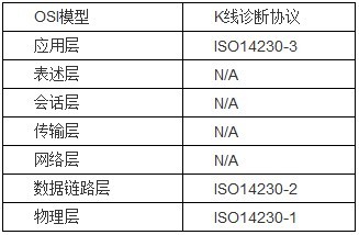
Table 1 Correspondence between ISO14230 and OSI models
The physical layer defines the correspondence between logical bits and physical levels, and defines the rise and fall times of the signal bits. The data link layer protocol defines the K-line data format, diagnostic message format, timing parameters, and communication error determination. The processing mechanism, the application layer protocol defines a request/response based diagnostic process and various diagnostic services. As the ECU node to be diagnosed, the main functions of the K-line protocol driver are:
1. Encapsulate and send, receive, and parse diagnostic messages, and fill/extract SIDs and data according to the message format;
2. Establish diagnostic communication with the diagnostic instrument through the initialization process;
3. Return the corresponding diagnostic response according to the diagnostic request of the diagnostic device and the current state of the ECU, and manage the diagnostic session;
4. Maintain correct inter-frame timing, inter-byte timing, detection of timing errors of diagnostic instrument messages and other communication errors;
The following describes the principle and implementation of the K-line diagnostic protocol driver in combination with the protocol analysis of the data link layer and its data structure and driver design.
2 protocol driver design
The K-line is based on an asynchronous serial communication interface. The SCI serial data link format of 8N1 format is used in the underlying transmission: 8 data bits + 1 stop bit, no parity, since the K line is a single root on the physical layer. The line also triggers the reception interrupt when transmitting, so the transmission and reception analysis of the K-line message is unified in the SCI reception interrupt processing function in the form of a state machine [3]. The following describes the implementation of the data link layer from three aspects: packet transmission and reception, resolution, initialization, and timing management.
2.1 Packet Sending and Receiving and Parsing
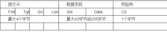
Table 2 K-line diagnostic message structure
The K-line message consists of a message header, a data field, and a checksum. The packet header includes a format byte Fmt, a destination address Tgt, a source address Src, and an optional additional length information Len. Fmt specifies a form of a target address (physical address/function address) when the packet header does not include an optional Len field. Specifies the length of the data field; the data field includes the service identifier Sid and the data Data, the length of which is determined by Fmt and Len; CS is a single-byte checksum. The design message structure is as follows:
Typedef struct
{
K_state state;
Uchar fmt;
Uchar tgt_addr;
Uchar src_addr;
Uchar datalen;
Uchar sid;
Uchar *data;
Uchar checksum;
Uchar msgdatalen;
Uchar done;
}k_msg;
Typedef enum{
k_FMT=0,
k_TGTADDR,
k_SRCADDR,
k_DATALEN,
k_SID,
k_DATA,
k_CS
}k_state;
The member variable state indicates which component of the message the current K-line communication data is, msgdatalen is used for the statistics of the number of bytes of the data field, done indicates whether the message is sent or received, and other member variables and the packet structure component are A correspondence.
Void k_ifc_rx(void)
{
K_u8 ch, SciSr1;
SciSr1=Kline_periph[SCISR1];
Ch=Kline_periph[SCIDRL];
TimerStop(k_TP4);
Switch(k_curmsg.state){
Case k_FMT:
If(k_REP==k_drvhandle.mode){
If(ch==k_curmsg.fmt){
K_curmsg.state=k_TGTADDR;
k_SendChar(k_curmsg.tgt_addr);
}
}else{
K_curmsg.state=k_TGTADDR;
K_curmsg.fmt=ch;
}
Break;
Case k_TGTADDR:
...
Break;
Case k_SRCADDR:
...
Break;
Case k_DATALEN:
If(k_REP==k_drvhandle.mode){
If(ch==k_curmsg.datalen){
K_curmsg.msgdatalen=0;
K_curmsg.state=k_SID;
k_SendChar(k_curmsg.sid);
}
}else{
K_curmsg.msgdatalen=0;
K_curmsg.datalen=ch;
Free(k_curmsg.data);
K_curmsg.data=malloc(k_curmsg.datalen);
K_curmsg.state=k_SID;
}
Break;
Case k_SID:
If(k_REP==k_drvhandle.mode){
If(ch==k_curmsg.sid){
K_curmsg.msgdatalen++;
If(k_curmsg.msgdatalen==k_curmsg.datalen){
K_curmsg.state=k_CS;
k_SendChar(k_curmsg.checksu);
}else{
K_curmsg.state=k_DATA;
k_SendChar(k_curmsg.data[0]);
}
}
}else{
K_curmsg.sid=ch;
K_curmsg.msgdatalen++;
If(k_curmsg.datalen==k_curmsg.msgdatalen){
K_curmsg.state=k_CS;
}else{
K_curmsg.state=k_DATA;
}
}
Break;
Case k_DATA:
...
Break;
Case k_CS:
K_curmsg.state=k_FMT;
If(k_REP==k_drvhandle.mode){
If(ch==k_curmsg.checksum){
K_curmsg.done=1;
}
}else{
K_curmsg.checksum=ch;
K_curmsg.done=1;
}
Break;
} if((k_REQ==k_drvhandle.mode)&&(k_FMT!=k_curmsg.state)){
TimerStart(k_REP_P4MS, k_TP4, 0, 1);
}
}
2.2 Initialization
Before starting the diagnostic service, the diagnostic device must initialize the ECU, obtain the message header format and timing parameters supported by the ECU through the response of the ECU, and establish a diagnostic communication [4]. The initialization process is shown in Figure 1. The diagnostic device sends a 25ms '0', 25ms '1' WuP (WakeUp Pattern), and then sends an STC (StartCommunication) Request. The ECU detects the WuP and receives the correct STC Request and returns to the STC. Response, the Data field of the message is a "Key Word" consisting of two bytes, which specifies the message header and timing parameter information supported by the ECU. For example, if Key Word is specified as 0x8fea, it means the message. The header uses the additional length information Len to indicate the length of the data field, while using the default timing parameters.
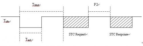
Figure 1 initialization process
Before the initialization, the K line is idle. The ECU disables the SCI function and enables the RXD pin of the SCI to be in the IO mode. When the falling edge is detected, the duration of the IO low level of the RXD pin is counted by the timer. When the rising edge is detected. Start counting the IO high level duration of the RXD pin to determine whether it is a valid WuP. You can also set the SCI baud rate to 200bps to determine whether it can receive data 0xf0 (0xf0 is represented on the bus as 5 0,5 1) After detecting the correct WuP, enable the SCI function, set the baud rate to 10400 bps, wait for the STC Request sent by the diagnostic device, return to the STC Response after receiving the request, and establish a diagnostic communication.
2.3 Timing Management
ISO14230 defines four timing parameters to manage inter-byte timing and inter-message timing. The diagnostic instrument and ECU need to comply with these timing constraints to ensure normal diagnostic communication. Table 2 gives the meaning and value of these four timing parameters. Interval.
Parameter variable description minimum (ms) maximum value (ms)
Inter-byte time interval 020 of P1ECU response
The time interval between the P2 diagnostic device request and the ECU response, or the time interval between two ECU responses 2550
The time interval between the P3ECU response and the diagnostic request is 555000
Inter-byte time interval 020 requested by the P4 diagnostic device
Table 2 Timing parameters
P1 and P4 are the inter-byte timings in the message, and P2 and P3 are the inter-message timings. The diagnostic device needs to send a diagnostic request within P3 after the initialization is completed or after receiving the diagnostic response. Otherwise, the ECU exits the diagnostic session, disconnects the diagnostic communication, and the K-line protocol driver restarts, waiting for the diagnostic device to issue the next WuP and STC Request. After receiving the diagnostic request, the ECU needs to return the diagnostic response within P2 time. P2 is controlled by the ECU, usually with a fixed value of 25ms. When the Fmt field in the diagnostic request message specifies the target address as the "function address", P2 The value needs to be generated by a random number generator, because for a functionally addressed diagnostic request, multiple ECUs may return a response. If a fixed P2 parameter is used, it may occur because multiple ECUs compete for the bus. Bus conflict problem, P2 uses random number, ECU will not return response at the same time, thus avoiding bus competition.
3 protocol driver test
The protocol driver is tested on Vector's CANoe software and hardware platform. When K-based KWP2000 service test is performed, KWP2000.dll and KLineCPL.dll modules are added to the CANoe simulation environment, CANoe simulates the diagnostic node, and a proxy node is used. The message forwarding between the CAN network and the K line is realized. At this time, CANoe uses the serial port of the computer and is connected to the ECU through the serial port/K line converter. The diagnostic implementation framework is shown in FIG. 2 .
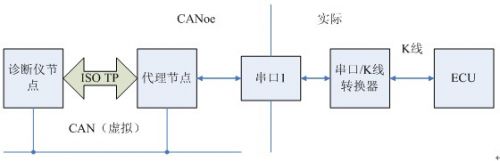
Figure 2 K-line diagnostic framework
Different from the CAN bus diagnosis, the K-line diagnosis requires the diagnostic instrument to establish diagnostic communication through the initialization process and the ECU. The establishment of the diagnostic communication is shown in Figure 3. After the diagnosis communication is established, the diagnosis service can be performed like the CAN diagnosis. There are many papers in this area, and will not be described here.
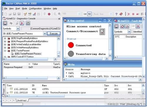
Figure 3 Establish diagnostic communication
Conclusion
The K-line protocol driver module implemented in this paper has been rigorously tested to efficiently perform K-line diagnostics, and the performance and stability meet the expected design requirements. The driver is independent of the processor and operating system, has good versatility and flexibility, can be easily integrated into the application, has high practical value and reference.
12V Power Supply is suitable for LED, Electronic cigarette, Tablet, Water purifier, Router, CCTV camera, LCD, Motor, Fan, Toys Medical machine, POS machine, Beauty & Health equipment, Humidifier, LED lights etc.
We can meet your specific requirement of the products, like label design. The plug type is US/UK/AU/EU. The material of this product is PC+ABS. All condition of our product is 100% brand new. You can send more details of this product, so that we can offer best service to you!
12V Power Supply
12V Power Supply,12V Pc Power Supply,12V Dc Power Supply ,12V Power Supply For Pc
Shenzhen Waweis Technology Co., Ltd. , https://www.waweis.com