
1 Introduction
This article refers to the address: http://
The concept of Virtual Instrument was first proposed by National Instruments [1], and its core technical idea is that "software is an instrument." It changes the measurement mode of traditional instruments, allowing the measurement system to evolve from a loosely coupled, often incompatible, stand-alone instrument into a tightly coupled virtual measurement system. When the user's test requirements change, it is convenient for the user to increase or decrease the hardware, software modules, or reconfigure the existing system to meet the new test requirements. This way, when users move from one project to another, they can simply construct a new VI system without losing its own hardware and software resources.
At present, the substantial increase in the number of cars in the city has brought great convenience to people's daily life, and it has also brought serious environmental problems. The exhaust gas generated by it has already constituted a public hazard, so the monitoring of motor vehicle exhaust has been Become an important indicator of environmental pollution. This paper designs a system based on virtual instrument for gas concentration detection. It uses NI PCI-6221 data acquisition card to collect gas detection data, and uses NI LabVIEW software to process data.
2 Virtual Instrument Overview
The virtual instrument is an electronic test instrument based on computerized functional hardware modules and computer software, and the software is the core of the virtual instrument (as shown in Figure 1). The basic part of the software is the device driver software, and these standard instrument drivers The software makes the development of the system independent of the hardware changes of the instrument. This is one of the biggest advantages of virtual instruments. With this, the development and replacement time of the instrument will be greatly shortened.
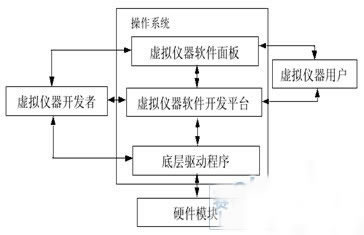
Figure 1 virtual instrument development block diagram
Unlike traditional instruments, virtual instruments have their own advantages:
It can achieve more complex functions by operating on several sub-panels. In this way, the simplification of the functional operation and the simplification of the panel arrangement can be realized on each of the sub-panels, thereby improving the correctness and convenience of the operation. Designers can design instrument panels based on user requirements and operational needs. The designer can design the instrument panel according to the user's requirements and operation needs; the function of the instrument is defined by the user according to the need, not defined by the manufacturer in advance; the virtual instrument is open, flexible, and synchronized with the computer, with the network and other Peripheral equipment interconnection; because it is based on PC, with the support of software, it uses the powerful data processing function of PC CPU; it can conveniently store and exchange test data, and the expression of test results is more diverse.
3 system components
The composition of the detection system is shown in Figure 2.
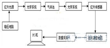
Figure 2 Measurement system structure
The infrared light emitted by the light source merges into a parallel beam through the front optical system, and then the parallel light passes through a gas pool through which the gas to be tested passes. The measured gas will absorb infrared light of a specific wavelength, and the light energy (light intensity) of the infrared radiation changes. (Light intensity is reduced). After the absorption of the gas and then through the convergence of the rear optical system, the light is concentrated on the infrared detector of the multi-probe [2]. When there is no interaction between the various mixed gases, and the absorption spectra are not overlapped or the influence is small, a narrow-band filter suitable for analyzing the absorption wavelength of the gas may be placed in front of the sensor, and after the filter is filtered, the infrared detector takes the component to be tested. The absorbed residual light energy is converted into an electrical signal, which is filtered and amplified by the signal conditioning circuit and sent to the computer through the acquisition card for data analysis. The difference between the incident light intensity and the outgoing light intensity is related to the concentration of the gas, from which the concentration of the gas can be detected.
Modern automatic detection and automatic control are inseparable from the sensor. It is the primary link of the test and control system. It can directly convert the measured physical quantity into an electrical signal output with a certain corresponding relationship and easy to detect to meet the information. Analysis, processing and other requirements. This system selected Heimann's TPS4339 thermopile detector. It is mainly used to detect the change of the light energy at the absorption wavelength of the gas to be measured.
Data acquisition is based on PCI-6221 data acquisition card introduced by National Instruments. It is based on computer PCI bus technology and belongs to M series card. It only supports DAQmx data acquisition method. The PCI-6221 provides 16 analog inputs with 37-pin D-Sub and a 16-bit A/D converter with a sampling rate of 250 kS/s [3]. Figure 3 shows the block diagram of the PCI-6221 data acquisition system.
The signal from the infrared sensor is sent to the data acquisition card through the CB-68LP terminal block and the SHC68-68-EP cable. The acquisition card performs A/D replacement on the collected signals, and then contacts the operating system through the NI DAQmx driver to collect the collected data for system analysis and processing.
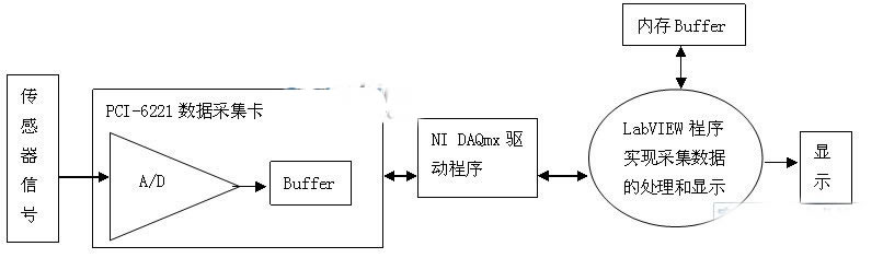
Figure 3 PCI-6221 data acquisition system block diagram
4 software design
After the detection system starts, first initialize each module, including the configuration of the acquisition card and the configuration of each acquisition channel; then determine whether calibration is needed. If calibration is required, a calibration window program will be displayed for calibration; if calibration is not required, the data acquisition will be directly entered; After the data is collected, it enters the data processing module; after processing, the result is displayed, thus completing one data acquisition and processing. The system is continuous acquisition, so it is judged whether to end the acquisition, if not, continue a new round of data collection and processing; if the acquisition is over, the program stops. Each time the collected data is stored in the database, it is convenient to query the previous data. As shown in Figure 4 is the operating interface of the system.
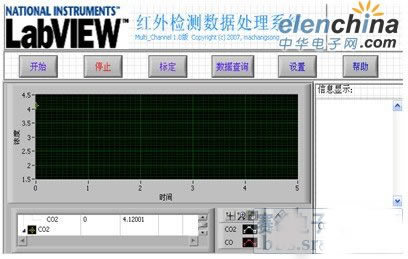
Figure 4 system operation interface
4.1 Calibration module
Whether the system calibration is accurate is related to the accuracy of the final result of the entire system.
After the calibration procedure is started as shown in Figure 5, the calibration gas and the calibration points are first selected for parameter setting. According to Lambert-Beer's law, the absorption rate of gas and the concentration of gas are linear. By passing a standard different concentration of gas to be tested into the gas pool, the absorption of infrared light is different, and the signal of the infrared sensor is different. The absorption curve is scaled by using a standard sample gas of different concentrations, and the accuracy of the absorption curve is improved by increasing the number of points to be calibrated. To start calibration, first input the standard concentration value of the standard gas used, and then collect the voltage data through the acquisition card. After the data is stable, save the two sets of data input, and then proceed to the next calibration point until the data of all calibration points is input. At this point, a set of data pairs is formed, and then the linear absorption curve of the gas is fitted. In the actual test, the data will be processed using the fitted absorption curve.
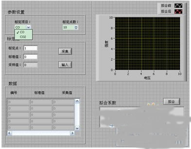
Figure 5 calibration module front panel diagram
4.2 Data Acquisition and Processing Module
In this paper, the acquisition card is used to collect the analog input signal. NI data acquisition card can be divided into three connection forms for analog signal input: differential, reference single-ended RSE, no reference ground. Non-Reference Single-ended NRSE [3]. General data acquisition must first configure the acquisition card according to the actual signal and acquisition equipment, and then use the LabVIEW VI module to design the acquisition program.
The signal of the sensor herein is a signal that is not connected to any ground (such as the earth or the ground of a building), that is, a floating signal. Moreover, the signal of the sensor is modulated by amplification greater than 1V, and all signals can share a common reference point. Therefore, the system uses a reference single-ended connection method to connect the signal reference point to the analog input ground of the instrument [4]. The system collects CO and CO2, as well as the reference light signal, so it is necessary to collect data continuously by three channels. Make the channel configuration program diagram a subVI to facilitate the calling of other programs.
The data collected by the PCI-6221 capture card is directly collected by three channels. In order to process the data of the three channels separately, the data of the three channels needs to be separated and saved separately. The data is saved to the database every time a complete acquisition is completed, making it easy to review historical data.
Since the delay caused by data analysis will increase the period of data collection, the queue is adopted, that is, the data collection loop collects data without interruption, and the collected data is placed in a queue, and the data analysis loop is continuously processed. data. If the period of the analysis data is greater than the collection period, the data will be cached in the queue. If the queue is not full, the data will not be lost. If the period of the analysis data is less than the collection period, the data analysis is in a wait state when the queue is empty. It also does not lead to repeated analysis of data; when the data collection cycle is stopped, if there is still data in the queue, the data analysis cycle will also analyze the remaining data, so that the previously collected data will not be lost [5].
4.3 Database Module
Because LabVIEW does not have database access, you can take advantage of LabVIEW's free LabVIEW database access toolkit LabSQL. LabSQL uses Microsoft ADO and SQL language to complete database access.
First, you need to create a database in Access, and then create the System Data Source Name. The data source manager under Windows Control Panel - Administrative Tools - Data Sources (ODBC) can be created and used as data. The source selects the Microsoft Access Drive (*.mdb) driver. In the pop-up ODBC Microsoft Access Setup dialog box, select the Access database that has been created, and the data source is created. In LabVIEW, ADO establishes a connection with the created DSN to access the Access database [6].
The database access of this system is mainly to realize the query of the previous data, and to provide reference data for atmospheric environmental pollution control. As shown in FIG. 6, the database records the data of the day on a date table, and each record in the table records the current detection time and the detected CO and CO2 gas concentration values. When querying, first select the database, then select the date to be queried, which is the table name. When querying, you can select either a single query or a combined query. For example, you can choose to query the concentration values ​​of CO and CO2 in the exhaust gas of the vehicle detected from October 16 to 16:30 on October 2, 2008. After the operation field and operating conditions are set, the combined query can be selected to obtain the qualified data.
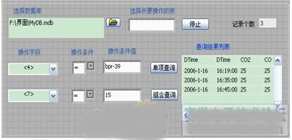
Figure 6 Front panel diagram of the database module
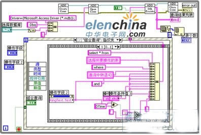
Figure 7 Rear panel program diagram of the database module
5 Conclusion
This paper uses the LabVIEW software as the platform to develop the vehicle exhaust gas concentration detection system, which can conveniently collect and detect the concentration of CO and CO2 gas, and analyze the concentration value of the polluted gas. The user interface is friendly, intuitive and easy to operate. LabVIEW itself is highly efficient in programming and can easily and quickly upgrade software systems. The test results of the system can not only monitor and evaluate the performance of the motor vehicle, but also provide reference data for the treatment of atmospheric environmental pollution, which is very suitable for the requirements of modern testing.
references
[1] Yang Leping, Li Haitao, etc. LabVIEW program design and application. Electronic Industry Press, 2001, 7:1~4
[2] Yu Yichao, Zhao Jianhua, Zhao Zhongwei. Research on a new non-dispersive infrared three-component gas analyzer. Automated instrumentation [J], 2006, 6: 70-73.
[3] DAQ M Series User Manual.http://
[4] Cai Chunli. Virtual Instrument Technology and Software Development Platform. LabVIEW. Journal of Chongqing Vocational and Technical College [J], 2004, 1 (34): 102-103.
[5] Du Yuling. Design of Data Acquisition System Based on LabVIEW and PCI-7422. Journal of Huaihai Institute of Technology (Natural Science Edition) [J], 2004, 1 (31): 15-17.
[6] Chen Xihui. LabVIEW 8.20 program design from entry to proficiency [M]. Beijing: Tsinghua University Press, 2007.
Shaded Pole Motor,Capacitor Motor Yc Series,Capacitor Motor Tl61,Shaded Pole Ac Motor
Wentelon Micro-Motor Co.,Ltd. , https://www.wentelon.com