
Introduction
With the continuous development of LED technology and the advent of white LEDs, the lighting industry has begun the era of green lighting. Because LED has low energy consumption, low heat radiation and high luminous efficiency, it is a new type of lighting device with energy saving, environmental protection, economy and safety. Therefore, accelerating technical research and improving its luminous efficiency have become the primary problems. High-power LEDs must become the mainstay of the lighting industry. Safe and efficient driving research is the key to promoting the application of high-power LEDs.
1 high power LED operating characteristics
LED is a new type of semiconductor solid-state cold light source, which is an optoelectronic device capable of converting electrical energy into visible light. In general, high-power LEDs have a power of at least 1 W. Currently, 1 W, 3 W, 5 W, 8 W, and 10 W are common; LEDs called “green light sources†are moving toward high currents. (300 mA to 1.4 A), high efficiency (60 to 120 lm/W), and adjustable brightness.
(1) volt-ampere characteristics
The high-power LED is a low-voltage, high-current driving device. When the LED voltage changes very little, the current varies greatly. When the forward voltage exceeds a certain threshold, commonly referred to as the turn-on voltage, it can be approximated that IF is proportional to VF, as shown in FIG.

(2) Light characteristics
According to the principle of LED illumination, the luminance of the LED changes substantially with the current of the LED. Controlling the brightness of a high-power LED is essentially controlling its output luminous flux.
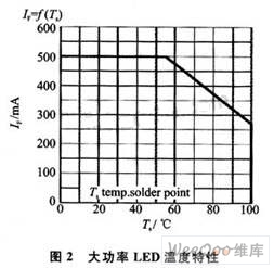
(3) Temperature
The magnitude of the LED forward current also varies with temperature. Once the ambient temperature exceeds a certain value, the allowable forward current of the white LED will be greatly reduced. In this case, if a large current is still applied, it is easy to cause the white LED to age. Figure 2 is a plot of temperature versus forward current for an LED.
2 system design
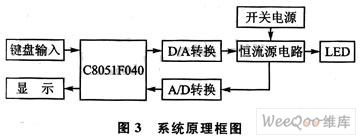
The stability of the light source system has a lot to do with the drive power, and many factors such as transient current or voltage spikes can easily cause damage. The performance of the drive power directly affects the operating life and stability of the entire light source system. The driving power required for high-power LEDs is the low voltage of DC. Therefore, the power source traditionally used to drive light sources such as light bulbs (tungsten filaments), port lights, energy-saving lamps, sodium lamps, etc. is not suitable for directly driving high-power LEDs. According to the above high-power LED characteristics, a small change in VF will cause a large IF change; if the current is too strong, it will cause the LED light to attenuate, if the current is too weak, it will affect the LED's luminous intensity; when the temperature rises, the LED's barrier potential will decrease. The current will get bigger and bigger. Therefore, the use of constant voltage source drive can not guarantee the consistency of LED brightness. And affect the reliability, life and light decay of LEDs, so super bright LEDs are usually suitable for constant current source driving. In addition, to improve the efficiency of lighting, design LED drive system with perfect and reliable protection function, intelligent LED drive with automatic control and detection becomes a necessary way for technological development. In this paper, the combination of hardware circuit design and software program design is adopted. The single-chip microcomputer is the core, and the output current is adjusted by negative feedback to achieve the purpose of stabilization, thereby completing the intelligent driving system suitable for various high-power LEDs with adjustable brightness. The performance of the system has been greatly improved and improved, effectively solving the problem of stability and reliability of the light source output. The system block diagram is shown in Figure 3.
2.1 Controllable constant current source
Figure 4 is a constant current source circuit used in the system. The circuit belongs to the topology of current series negative feedback, and is composed of an integrated operational amplifier and a MOS transistor. In order to achieve adjustable constant current source control, an adjustable voltage signal Vin outputted by D/A is introduced at the non-inverting input of the operational amplifier to make it a controlled constant current source. Connect the sampling resistor R to the reverse input terminal. The output current of the constant current source is directly dependent on the ratio of the output voltage of D/A and the sampling resistor R1, which is expressed as: Is=Vin/R.
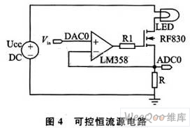
The integrated op amp LM358 includes two independent, high-gain, internal frequency-compensated op amps with high gain, low offset voltage, wide supply voltage range of 3 to 30 V, and can be used as a voltage follower. The op amp is matched with the MOSFET RF830 to follow the input voltage Vin through feedback. The base of the power MOSFET is connected to the output stage of the op amp to increase the drive current. When the input voltage of the LM358's non-inverting terminal is constant, due to the existence of negative feedback, the output voltage of the LM358 is guaranteed to be constant, so that the current flowing through the LED load is a constant current. The design is to adjust the input voltage Vin of the current source from 0 to 2.4 V under the condition of 0 to 30 V power supply, and control the constant current source circuit to obtain a current output of 0 to 2.4 A, thereby calculating the resistance of the sampling resistor. The value should be 1 Ω to guarantee the required constant current value.
The choice of sampling resistor directly affects the stability of the constant current source. When the output current reaches a certain level, R will inevitably cause heat to cause a change in its own resistance value, which is a key factor affecting the accuracy of the output current value of the constant current source. At the same time, the A/D conversion provides data by the closed-loop control of the single-chip microcomputer by the voltage value on the sampling R. Since the maximum output current of this design is 2.4 A, the power of R should be large enough. For this reason, a resistance of 1 Ω and a power of 10 W made of a constant temperature coefficient of a constant copper material was used. In addition, the MOSFET is a voltage-controlled device, and its gate control current IG is almost zero at steady state, which does not affect the accuracy of the output current UD, thereby ensuring the output current accuracy of the constant current source. For the MOSFET tube in the circuit, a high-power tube should also be selected to meet the current requirement. The system uses an N-channel enhancement MOSFET tube RF830 with a drain current of 4.5 A and a dissipated power of 74 W.
2.2 Automatic control unit
The design of the above controllable constant current source has met the requirements of the stable output of the power supply, but the stability of the power supply is only a necessary condition for the stability of the light source. Because the power supply output current will still fluctuate during long hours of operation when the power supply is stable. The automatic control module in the system is mainly composed of a single-chip computer (C8051F040) system with functions such as keyboard, LED digital display and A/D and D/A control. Four of the buttons (S1 to S4) control two functions, two selection buttons, and two addition and subtraction buttons. When the LED light source changes, the electrical parameters of the LED change and the required constant current value also changes. The desired current value of the current LED is set by selecting button 1; when the LED light source is fixed and controlled to reach a constant current operation, the S2 can easily set the LED brightness. The system circuit design principle is shown in Figure 5.
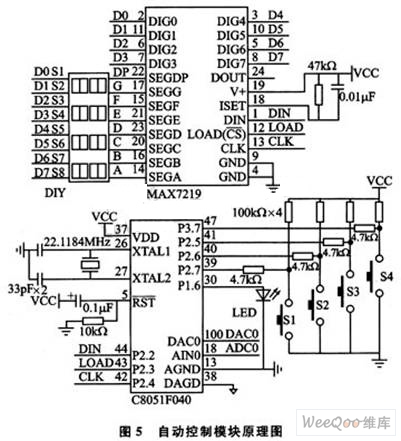
The main function of this section is to provide the precise voltage signal required to regulate the output current at a given current value. First, set the given current value using the keyboard input method. According to the data written by the MCU, the built-in 12-bit D/A conversion output DC voltage is supplied to the input voltage Vin of the constant current source to obtain a stable constant current output, and then the LED output is output through 12-bit A/D sampling. The current data is sent to the single chip microcomputer, and the control voltage is calculated by the single chip processing. According to the comparison between the actual current and the set current, new data is written to the single chip, thereby updating the output current, and then feeding back to the controllable constant current source circuit to realize the Accurate adjustment of the output current of the constant current source, and finally the value of the set current and the output current are respectively displayed by the digital tube.
As the core of the control system, the C8051F040 has built-in 12-bit A/D, D/A conversion, and built-in 2.4V reference voltage, which is more convenient for system circuit design. According to the reference voltage, the A/D output current is in one-to-one correspondence with the voltage range of the D/A input. The current accuracy obtained by 12-bit A/D conversion can reach 0.6 mA, which meets the design requirements.
3 system software design
The design of the software program mainly includes the initialization management module, the button management module, the data processing module and the display module. All modules are written in the C51 language of the single chip microcomputer. According to the hardware circuit, the main program flow of the whole MCU software part is shown in Figure 6.
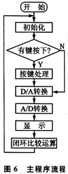
In the closed-loop comparison operation, the standard value is approximated by comparing the difference between the actual value and the set value. If the actual value is greater than the set value, the original D/A entry value is subtracted from the difference and sent to the D/A conversion; if the actual value is less than the set value, the original D/A entry value is added to the difference. The value is sent to the conversion. Cycle comparison, the actual value and the set value are consistent, and the stable actual value is displayed through the digital tube.
The performance index of the system is mainly determined by two relationships: the relationship between the set value and the A/D sample display value; the relationship between the internal measured value and the actual measured value. The latter is caused by the influence of the sampling resistor and the load resistance and the amplification factor of the transistor on the temperature and the error of the measuring instrument. In order to reduce this error, it is necessary to use a resistor with a low temperature coefficient as the sampling resistor; and the error of the A/D and D/A conversion process can be obtained through a number of experiments to obtain a certain proportional relationship, and the obtained error is added to the system program. .
4 data processing and results analysis
Data testing is an important indicator of system performance. This test selects 1 W, 2 W, 10 W LEDs, and sequentially supplies 9 V, 12 V, 15 V power supply voltages, and sets the output current value corresponding to the selected power LEDs by pressing the button (1 W-0.35 mA, 2 W -0.70 mA, 10 W-1 A), respectively detect the corresponding D/A conversion output voltage, the actual output current value detected by the current source itself, and the current value measured by the external ammeter and the two data display values ​​of the digital tube. Secondly, for the 2 W LED, the current is adjusted separately, and the voltage is changed in steps of 10 mA to observe the change of the brightness of the light. The relevant data are listed in Table 1 and Table 2.
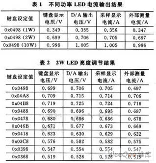
It can be seen from the above test results that the system realizes the precision constant current source controlled by the single chip C8051F040, which ensures the stable operation of the high power LED, and meets the requirements of the error accuracy of ±3 mA for the output current of different power LEDs. . In addition, when adjusting the brightness, it can be seen that when the current value is small, the output current is closer to the given current; when the current value is large, the performance of the constant current source power supply is degraded due to the insufficient heat dissipation performance of the system, causing an increase in error. The reason for the error is mainly the sampling resistor manufacturing error, while the sampling resistor is hot when the system is working, and the resistance value will also cause errors. But in general, the system has high stability and accuracy.
Conclusion
The system is controlled by a single-chip microcomputer, which effectively improves the current stability of the light source output. The intelligent control of digital light source driving is realized, which has great significance for the development of high-power LED lighting. In terms of data testing and debugging, due to the error of the instrument and the error caused by the temperature rise of the circuit device due to the long working time, the measurement data is not very accurate. The software design is used to minimize the error, so that the error of the output current The range is reduced to ±2 mA, which greatly improves the accuracy of the system.
:
Auto Tail & Licence Plate Light
Tail light is a red light on the back of a car that makes it possible for the vehicle to be seen in the dark. Licence plate light bright sign on a vehicle that shows its registration number. The rear lights are shown in the front of the car in front of the vehicle and show the location of the two workshops, so they are mounted on both sides of the vehicle. Japan's safety regulations are the same as those of European standard ECE7. The light intensity near the center is 4~12 CD and the light color is red. 1. With sufficient light intensity, the car taillight can clearly distinguish the signal from the driver or pedestrian of other vehicles even in bright sunlight. 2, night driving, tail lights light will not produce glare to other vehicle drivers or pedestrians and uncomfortable feeling As the ideal tail lights should have the following characteristics: (1) high luminous intensity and reasonable distribution of light intensity; (2) fast forward time of luminous rise; (3) long life, no maintenance, low energy consumption; (4) strong switch durability; (5) good impact resistance.
Auto Tail & Licence Plate Light
Auto Tail,Licence Plate Light,LED Tail Light,Waterproof Licence Plate Light
Heshan Jianhao Lighting Industrial Co., Ltd. , http://www.sunclubtw.com