
1 Introduction There is often a blind spot in the corner of the curve. The driver can't see if there is a vehicle passing by the road, which causes a lot of traffic accidents. Therefore, it is especially important to eliminate the traffic accident caused by the blind spot. To this end, a mountain road turning warning system based on C8051F310 was designed. When detecting that there is a car on the opposite side of the detour, the system can promptly alert the driver to avoid the traffic warning light. Therefore, accurately determining whether a vehicle passes is the key to the design of the system.
This article refers to the address: http://
2 system design
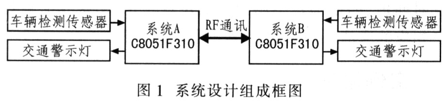
2.1 System Design The main purpose of the system design is to alert the driver to safety and prevent accidents while driving. The system is placed on both sides of the turn of the mountain road, and each side of the system controls a warning light. When one of the systems detects the vehicle, it sends it to the other party's system through RF communication. After the other party's system receives the signal, the control warning light flashes to alert the driver.
Figure 1 is a block diagram of the system design. Among them, the vehicle detection sensor uses a sine wave oscillation circuit to detect the vehicle. In the detection circuit, the output signal frequency is collected by C8051F310, and then processed by a first-order filtering algorithm to filter out frequency interference caused by environmental factors, and further verify and verify. Acquisition accuracy of the C8051F310.
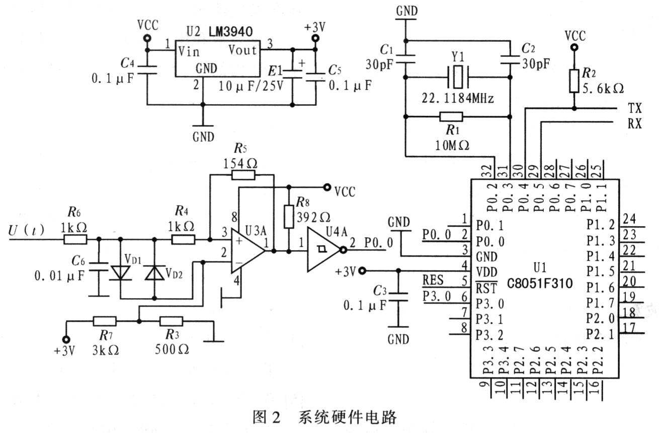
2.2 System hardware circuit design Figure 2 shows the system's main hardware circuit. The input signal of the vehicle detection sensor is U(t). After the sinusoidal signal is converted into a square wave signal by the comparator, it is input to the single chip C8051F310, and then the single chip acquires the signal frequency through the counter.
2.3 First-order filtering algorithm First-order filtering, that is, first-order inertial filtering. The first-order low-pass filtering algorithm is: ![]()
In the formula, α is the filter coefficient, X(n) is the current sampled value, Y(n-1) is the last filtered output value, and Y(n) is the filtered output value.
The first-order low-pass filtering method uses the current sampled value and the last filtered output value to weight, and obtains an effective filtered value, so that the output has a feedback effect on the input. The filter coefficient is 0~1; the coefficient determines the weight of the new sample value in the current filtering result. The first-order filter coefficients can be fixed or automatically calculated according to a certain program algorithm. However, the first-order filtering algorithm cannot fully balance sensitivity and smoothness. Only look for a balance point and choose the best possible smoothness within the acceptable sensitivity range of the system design. That is, when the data changes rapidly, the filtering result can be followed up in time (sensitivity first); and when the data tends to be stable, when the fixed point oscillates up and down, the filtering result tends to be stable (stableness first).
2.4 Vehicle Detection Circuit Figure 3 shows the sine wave oscillation circuit. This circuit is used in vehicle detection circuit sensors to sense the presence of metal objects. The eddy current sensing method is used to directly connect the buried detection line to the sine wave oscillation circuit.

When a metal object such as a vehicle is not detected, the frequency of the oscillation circuit output signal u0(t) does not change substantially, but the value does not remain constant, but drifts within a certain range. When a metal object such as a vehicle is detected, the frequency f0 of U0(t) is abruptly changed to f. The frequency difference Δf = f - f0, wherein the range of Δf is generally a few hundred hertz to several kilohertz by a large number of experiments. The oscillation frequency of the circuit in Figure 3 is:
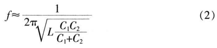
Where f is related to L, C1, C2 in the circuit.
When the value of the inductance L changes, f also changes accordingly. Similarly, when the capacitance value changes, f also changes. In general, the capacitance value changes with the ambient temperature, so the oscillation frequency f also changes with temperature.
2.5 Detection circuit frequency algorithm Because the signal frequency in the detection circuit changes at any time, it is difficult to detect metal objects such as motor vehicles, especially when the ambient temperature changes abruptly, the frequency value of the signal itself will change greatly. The analysis of the oscillating circuit data collected in the outdoor environment at high temperature shows that the f value changes by several hundred Hz with the temperature within 1 h, and no metal objects approach during the measurement. Therefore, the design uses a baseline dynamic change method. The specific calculation method is as follows: set fz as the reference frequency; fc is the acquisition frequency participating in the calculation and judgment; f is the actual acquisition frequency. m and n are filter factors. When the system is not powered, the initial value of fz is 0. After power-on, the frequency f acquired in the first time is taken as the initial value of fz, and then the fz value is periodically changed.
First, the actual acquired frequency f is first-order filtered according to equation (2), and then the value of fc is calculated:

The filter factors m, n in the equations (3) and (4) are obtained by experiments. When the f value changes rapidly, the filtering result is followed up in time and the data changes faster, and the sensitivity is higher. When detecting the vehicle, it is necessary to replace fz regularly, and change the time according to the outdoor temperature change.
When a metal object passes through the coil, the frequency value acquired is f, and the reference frequency is fz. The algorithm for judging the vehicle is south (3) to get fc, and then from equation (5):

The vehicle passing condition is obtained by judging whether Δf is in the same range. This paradigm is derived from a large number of experiments. The specific CPU algorithm flow is shown in Figure 4.

3 Experiment and result analysis The algorithm was obtained through a large number of verification experiments. Indoors, the test used a 45 cm × 45 cm coil (number of turns n = 12). The simulated motor vehicle is a metal trolley that is 1.2 m long and 0.8 m wide. When the trolley passes the coil, the difference between the acquisition frequency fc and the reference frequency fz is about 400 Hz, and the CPU can accurately determine that the trolley has passed. In the outdoor test, the coil is buried under the road surface. When the car passes through the coil, the difference between the acquisition frequency fc and the reference frequency fz is about 400 to 2 000 Hz. This difference varies with the vehicle model and the height of the vehicle chassis, and the CPU can accurately determine the passing of the vehicle. Through a large number of experiments indoors and outdoors, the filtering factors in the filtering algorithm are adjusted in time, and the detection sensitivity is improved to meet the needs of different vehicles.
4 Conclusion Using the filtering algorithm and updating the reference frequency of the oscillating circuit in real time can reduce the interference of the circuit frequency change on the vehicle detection. The mountain road turning prevention warning system designed with c8051F310 is now installed on Panshan Road. The system can accurately detect the vehicle and send warning information. At the same time, the design has a full consideration of environmental factors and maintenance inconvenience, and the design has a host computer monitoring system. Therefore, the system has simple structure, reliable performance and low price, which has caused widespread concern in the transportation sector.
Inverter AC/DC pulsed TIG welding machine
Welding Machine,Tig Welding Machine,Welding Machine Ac
Shitong Welding Equipment Co., Ltd. , http://www.tzweldingmachine.com