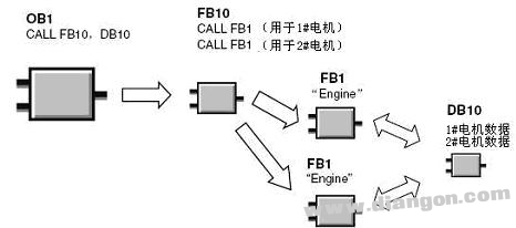
Multiple instance data blocks are a powerful feature in PLC programming that allows a single function block to be used multiple times with different sets of parameters. For example, if you call FB10 from OB1 and then call both FB1 and FB2 from within FB10, you can set the background data block of FB10 as a multiple instance data block. This way, FB1 and FB2 do not need their own individual instance data blocks; instead, their interface parameters are stored in the multiple background data block of FB10.
The process of creating multiple instance data blocks is straightforward. In the data type options, simply select "DB of the instance" for the function block. This approach helps reduce the number of data blocks needed when working with multiple instances of the same function block.
Let’s take an example: suppose you want to control two motors with identical interface parameters. Normally, you might create a function block FB1 and assign separate data blocks DB1 and DB2 for each motor. However, by using multiple instance data blocks, you can eliminate this redundancy. Instead, you can call FB10 in OB1, which then calls FB1 for each motor. Each call stores its specific data in the instance data block of FB10, eliminating the need for multiple standalone data blocks.
This method is especially useful when dealing with a large number of similar devices or processes. By centralizing the data storage in one background data block, you simplify the program structure and make it more efficient.
To implement this, first, insert a function block FB10 and a data block DB10. Set DB10 as a multiple background data block for FB10. Then, in the local variable definition window of FB10, define variables in the "STAT" area for each motor. Assign these variables the data type "FB" and specify the function block (e.g., FB1). The system will automatically calculate the memory addresses based on the number of interface parameters.
Once defined, the background data block DB10 will contain all the necessary data for each motor. For example, address 2.0–8.0 could hold the interface parameters for the first motor, while 10.0–16.0 could store those for the second. This setup ensures that each motor is controlled independently through the same function block, using different data sections within the same data block.
In the instruction list of FB10, you'll see two partial backgrounds representing the two motors. You can then call these partial backgrounds in your program to control each motor separately. This approach simplifies the code and improves maintainability, making it easier to manage multiple instances of the same function block.
By leveraging multiple instance data blocks, you can significantly reduce the complexity of your PLC program, streamline data management, and enhance overall efficiency. This technique is widely used in industrial automation to handle repetitive tasks with minimal overhead.

Battery test board assembly design,Battery test board PCB assembly,Battery test PCB design,circuit board printing service
Dongguan Jinglin Communication Technology Co., Ltd. , https://www.jlpcba.com
