
Electric vehicles (EV), hybrid electric vehicles (HEV) and fuel cell vehicles (FCEV) have good application prospects and economic benefits [1-2], and the application of HEV may reach a larger scale in the current period. Many companies and research institutes have made in-depth research on HEV. The key technologies that are different from ordinary cars are: battery [3]; motor and its drive system [4]; system energy management [5].
This article refers to the address: http://
The motor and its drive system are key components of the HEV. First, its high reliability must ensure long-term reliable operation of HEV. Second, system efficiency has a decisive influence on the energy consumption level of HEV. Nowadays, there are variable frequency speed control systems based on permanent magnet motors and induction motors (hereinafter referred to as inverters). Based on permanent magnet motor inverters, Japanese companies such as Hitachi and Kawasaki are the most mature products; based on asynchronous motor inverters, ABB, SIEMENS, ALSTON and other famous European companies are able to provide application systems with different power levels. In the electric locomotive market, product application and development trends are also consistent. This paper studies the inverter based on asynchronous motor. The supporting motor is YQ57 type variable frequency traction asynchronous motor produced by Xiangdian Electric Co., Ltd., which is applied to XD6120 HEV passenger car of Xiangdian Electric Co., Ltd.
Different from common industrial applications such as fans and pumps, the key requirements for inverters used in HEVs are: reliable structural design, convenient installation and maintenance, high protection level, and adapt to harsh environments.
1 Electrical system design
The electrical system of HEV mainly consists of three parts: battery, motor and inverter. The electrical system design process is described in detail in Ref. [6], and the parameters of these three parts are also described and analyzed in detail.
(1) Determination of basic motor parameters: The power and torque parameters of the motor should be determined according to the speed requirement, torque characteristics and transmission ratio of the HEV. Finally, the motor power of the XD6120 hybrid electric vehicle is 57kW, and the rated speed is 2000r. /min, the maximum starting torque is 2Tn.
(2) Voltage level determination: Since the safety factor of the automobile is the first factor, the IGBT applied to the HEV is the most widely used in the 600V and 1200V series. To determine the level of battery and motor voltage, the following factors should be considered: IGBT may generate overvoltage when it is turned off, so the DC side voltage of 600V series IGBT is lower than 400V when it is actually used; the battery voltage is floating, according to general requirements, the highest voltage It is equal to 120% of the rated voltage; when the power is the same, the higher the voltage level, the smaller the current, the smaller the volume of the motor and the inverter. Based on the above factors, the voltage level of the battery is determined to be 312V, and the voltage level of the motor is 230V.
(3) Other parameters are determined: after the battery voltage is selected, the battery safety time should be selected according to the requirements of the HEV's cruising range; the inverter current is calculated according to the motor current; the protection switch is selected according to the system voltage and current level. Its fuses, wire and cable model specifications, insulation and clearance of various electrical systems.
2 Inverter design key technology
Key technologies for inverter design include: main circuit parameter calculation; heat sink and fan calculation; digital control circuit design and software design; overall structural design.
2.1 Main circuit electrical diagram and main device parameter calculation
The inverter uses a voltage source type main circuit, a DC side plus a supporting capacitor, and an additional DC relay and a precharge circuit. Its circuit diagram is shown in Figure 1.
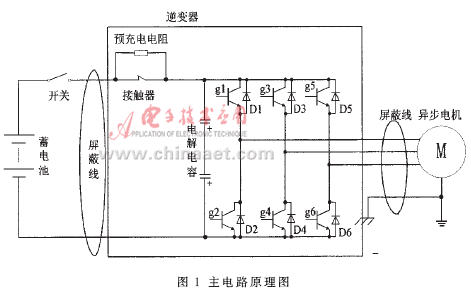
In the main circuit design, the most important thing is to determine the voltage and current levels of the power device. The IGBT voltage level selected by this system is 600V, the corresponding battery voltage level is selected as 312V, and the rated motor current is In=192A. Considering that the required starting torque is 2Tn at low speed start, the corresponding motor starting current is about 2In, so the starting current of the corresponding motor is about 2In. The current rating of the IGBT is chosen to be 600A.
The DC side capacitor voltage level is selected to be 450V depending on the selected voltage level. Its capacity is generally calculated using the following empirical formula [7]:
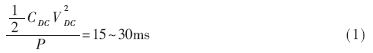
In the formula, P is the inverter output power, VDC is the DC side voltage, and CDC is the DC side capacitance capacity. The required capacitance is calculated to be 0.0175F ≤ CDC ≤ 0.035F. The capacitance capacity in the actual system is 20000μF.
2.2 Power device loss calculation [8]
The loss of the power device consists of four parts: IGBT static loss, IGBT switching loss, diode static loss and diode dynamic loss.
(1) The formula for calculating the static loss of IGBT is:
![]()
Where ICP is the rated output current; Vce(sat) is the saturation voltage drop at the rated output current; D is the average duty cycle; cos θ is the power factor.
(2) The calculation formula of IGBT switching loss is:
![]()
Where fC is the switching frequency; PSW(ON) is the IGBT turn-on energy consumption; and PSW(OFF) is the IGBT turn-off energy consumption.
(3) The formula for calculating the static loss of the diode is:
![]()
Where Vec is the diode conduction voltage drop.
(4) The formula for calculating the dynamic loss of the diode is:
![]()
Where: Irr is the diode reverse recovery current; trr is the diode reverse recovery time.
Based on the above four items, the calculated maximum loss is 1350W.
2.3 Digital Control Circuit Design and Control Software Design
The control algorithm of the inverter is completed by a digital control circuit. The digital control circuit includes two parts: a power supply and a power device driver board and a digital control circuit board.
The core chip of the digital control board uses TI's TMS320F240, which receives external commands, detects external analog signals, completes complex digital control algorithms, generates PWM pulses, uses CPLD chips as peripheral interface chips, and uses AMP waterproof sockets to receive external signals.
Since the speed and torque conversion range of the HEV transmission system is very large, the system uses rotor field oriented control with speed sensor. This control is described in detail in reference [9], and a complete DSP algorithm implementation is given.
3 system reliability design
For HEV vehicle inverters, the working environment is very poor due to the installation position under the vehicle. The specific performance is as follows:
(1) The difference in ambient temperature is very large, and the temperature that has been monitored in the actual operation test is up to 50 ° C, and the lowest is -10 ° C;
(2) The working environment is dusty when the weather is fine, and there is rain when it is raining;
(3) The inverter needs to withstand strong shock and vibration.
In order to ensure the safe operation of the vehicle, the reliability design of the system is the most important.
3.1 Radiator and fan calculation
After calculating the loss of the power device, the heat sink and fan can be determined based on the loss. To this end, using the thermal analysis software FLOTHERM for simulation calculations, the simulation results require that the radiator temperature rise below 30K.
Software calculation results: Table 1 shows the physical structure and parameters of the radiator; Table 2 shows the air volume and wind pressure calculation results of the fan; Table 3 shows the temperature values ​​of the five test points selected on the radiator.
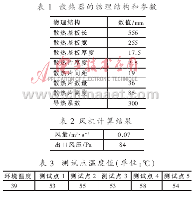
According to the software simulation calculation results, the radiator selects the brazed aluminum radiator, and the fan selects EBM's EBM6224N.
3.2 Integrated structural design
In order to reduce the weight, the outer casing is made of aluminum alloy material, which is good in strength and light in weight. Minimize the size of the structural design, so use an integrated structural design.
(1) The driving board is directly crimped to the IGBT;
(2) The DC side capacitor is directly connected to the IGBT through the composite busbar.
Reduce the inductance;
(3) The fan is directly installed at the bottom of the radiator;
(4) The digital control circuit board is mounted on an aluminum casing for easy disassembly.
After using the integrated structure design, the maintenance time of the system is greatly shortened. The AMP connector is used for the connection between the digital control board and the external signal. It is reliable and easy to assemble and disassemble. The connection between the power supply board and the IGBT uses an easy-to-remove pin connection. All disassembly work and replacement work can be completed in 5 minutes. Due to the simple system configuration, the repair work is also very simple, only the damaged circuit board needs to be replaced. So all work can be done in a very short time.
3.3 Wide range of operating temperature design
Due to the different environments, the actual working environment temperature may be worse than condition (1), which requires the inverter to adapt to a very wide working temperature. The system is designed with full consideration of the use environment, and the inverter must be able to work reliably for a long time in production and factory tests. Specifically, the following measures were taken:
(1) The operating temperature range of the selected device is -40 ° C ~ 85 ° C, and all devices are screened;
(2) Conducting a 24 hour power-on test for all power devices;
(3) After the test of the circuit board is completed, the low temperature storage at -40 ° C for 48 hours test;
(4) After the test of the circuit board is completed, the high temperature storage at 80 ° C is carried out for 48 hours;
(5) After the test of the circuit board is completed, the high-temperature cycle test at -40 ° C and 85 ° C is carried out, and the test is performed for 3 times for 24 hours;
(6) After the completion of the assembly of the inverter, the rated working condition test is carried out for 4 hours; the test result requires that the temperature rise of the radiator be below 30K;
Through the above measures, the inverter can be operated in a wide temperature range.
3.4 Waterproof and dustproof design
Considering that the inverter is installed under the vehicle, the working environment is very poor, there is rain and dust, so the system must be designed with waterproof and dustproof structure.
(1) Sealing waterproof rubber between the casing and the heat dissipation base;
(2) The motor cable is connected to the internal power device through a waterproof socket;
(3) The external control power supply and power line are connected through the AMP waterproof socket and the internal control circuit board;
(4) Forced air cooling of the radiator using EBM's waterproof fan, whose control line is connected to the internal control circuit board through a waterproof socket.
These measures are adopted to make the overall protection level of the system reach IP55. During use, the inverter can be flushed with water. Although the external part of the inverter is dust due to environmental factors, it does not affect the normal operation of the inverter.
3.5 Special design on software
In order to make the inverter suitable for HEV, the software also has some special designs: the control mode is open loop torque control; the limit torque change rate is made, the driver feels that the acceleration and deceleration are very stable; the temperature of the motor and the inverter is limited. Speed ​​to improve the system's reliable operation; limit the charging current to protect the battery. The special design on these softwares greatly improves system reliability.
3.6 Perfect protection function
Provides complete protection functions for the system: over-voltage and over-current protection for batteries, motors and power devices, over-temperature protection for motors and inverters, and timely response to power device faults to improve electrical system reliability performance.
4 laboratory testing
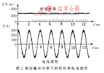
The rated power of the motor is 57kW, the rated torque is 270N·m, the rated speed is 2000r/min, and the rated terminal voltage is 230V. The inverter system parameters are matched according to the motor used. The torque and current waveforms when operating at rated power are shown in Figure 2.
Using the acquisition system to analyze the DC input voltage and current, AC output voltage and current, the inverter efficiency and motor efficiency are obtained. The specific data is shown in Table 4.
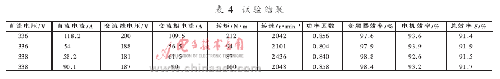
When the power is greater than 50%, the efficiency of the inverter is about 98%, the motor efficiency is about 93%, and the total system efficiency is greater than 91%. At low speeds and low power, system efficiency drops slightly.
5 real vehicle operation assessment
From July to August 2004, XD6120 HEV completed 56 final test and 7 000 km reliability driving test at Xiangfan Automobile Test Site of National Automobile Quality Inspection and Inspection Center. The report given shows that the car is fully compliant with various national mandatory standards, with good dynamic performance and obvious energy saving effect.
In October 2004, the XD6120 HEV participated in the 6th International Clean Energy Vehicle Bibendum Challenge at the Shanghai International Circuit and won the first place in the hybrid bus.
In July 2006, the demonstration operation on the Changsha No. 9 bus began. From the information returned from the demonstration operation, the reliability of the inverter and the motor is very high. For nearly a year, there was only one accidental record of on-site service. The reason is that the fan is blocked by muddy water, causing overcurrent damage to the fan control circuit.
The actual operation test shows that the inverter designed and manufactured by the above method has high reliability and is completely suitable for the harsh operating conditions of the HEV.
Ac Noise Filter,EMI Filter In Medical Devices,EMI Filter For Medical Appliance,Medical Device Filters
Jinan Filtemc Electronic Equipment Co., Ltd. , https://www.chinaemifilter.com