
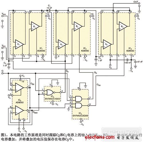
Some applications require the sampling of a set of analog voltages to be maintained, and at least two traditional methods are available to meet this requirement. The most common approach is to cascade a classic analog accumulator with a sample-and-hold amplifier. As shown in Figure 1.
The classic analog accumulator is an op amp plus at least three precision resistors. The values ​​of these resistors should be as low as possible to avoid affecting the bandwidth of the accumulator. But these low value resistors consume power. In addition, the structure of the accumulator and the sample-and-hold amplifier brings another disadvantage, which is manifested when the two input voltages have similar amplitudes and opposite polarities. At this time, even if the input voltage amplitude is high, the sum obtained is low, and if the input voltage amplitudes are equal, the sum is zero. Sampling low voltages usually results in relatively large errors in the output voltage because each amplifier has some dynamic error, such as residual parasitic charge coming into the storage capacitor.
There is also a possible way to use an amplifier per channel to summarize their outputs with a classic analog accumulator. Although this configuration avoids the problem that the input voltage amplitude is similar and the opposite polarity causes high output error, the precision resistor of the accumulator still consumes power.
These problems can be avoided by using the circuit structure of Figure 1, which does not use an external resistor. In steady state, the internal logic signal is active high during the internal tracking period, and the followers consisting of A1, B1 and A2 are enabled. Therefore, the ground referenced capacitor C2 is charged to the VINA voltage. The low side of capacitor C1 on IC2 Pin 2 is temporarily grounded through the output of the A2 follower, and it is connected to the high-end charge of IC1 Pin 9 to the VINB voltage. VINA and VINB are the input voltages for the A and B inputs, respectively.
After a stabilization period, when all internal logic control signals are low and all controlled followers are disabled, the QSB control logic signal is high. Since the follower B3 is enabled, the potential of the low side of C1 is from 0V to VC2(tS) = VINA(tS). VC2(tS) is the voltage value stored in capacitor C2, and then the signal transitions to an inactive low level. The high-end potential of C1 thus rises to VC2(tS) + VC1(tS) = VINA(tS) + VINB(tS), as shown in the lower waveform in Figure 2.
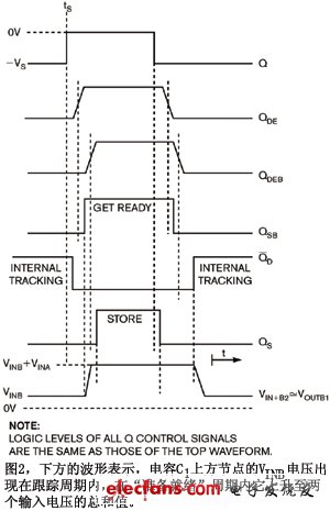
This waveform is the only analog waveform in this figure. The low-to-high effective conversion of the sampling command logic signal QS slightly lags behind the QSB logic signal, suppressing glitches on the output voltage. When QS is high, the sample voltage VINA(tS) + VINB(tS) appearing on IC2 Pin 7 is accessed by enable follower B2 and stored in capacitor C3 until the next sample instruction. Follower A3 acts as an impedance transformer. The dual op amp IC6 acts as a branch delay line that combines with a single NOR gate and a dual AND gate to derive a timing-correct internal logic control signal from a single external logic control signal Q.
Circular Connectors
Circular connectors, also called [circular interconnects," are cylindrical, multi-pin electrical connectors. These devices contain contacts that transmit both data and power. Cannon (now ITT Tech Solutions) introduced circular connectors in the 1930s for applications in military aircraft manufacturing. Today, you can find these connectors in medical devices and other environments where reliability is essential.
Circular Connectors is designed with a circular interface and housing to quickly and easily connect and disconnect signal, power, and optical circuits. Circular connectors are often preferred in military, aerospace, and industrial applications: these can be connected and disconnected without the use of coupling tools such as torque wrenches. Antenk`s circular connectors offer rugged solutions that have been engineered for reliable performance in a wide variety of harsh environment applications.
I/O Connectors provide secure electrical contact and smooth, safe disconnect. They are used across a range of industries for communications devices, business equipment and computers. Top considerations when purchasing I/O connectors include pinout, gender, voltage rating, contact plating, and termination style.
Types of Circular Connectors
Circular connectors typically feature a plastic or metal shell surrounding the contacts, which are embedded in insulating material to maintain their alignment. These terminals usually pair with a cable, and this construction makes them especially resistant to environmental interference and accidental decoupling.
Circular I/O Connectors Types
Audio Connector
BNC/TNC Connector
DC Power Connector
Mini Din Connector
Din Connector
M5/M8/M12/M16/M23 PP9 Connector
SMA/SMB/FME Connector
RCA Connector
MCX MMCX Connector
Circular I/O Connectors
Power Connector,Circular I Connectors,Circular O Connectors,Circular Power Connector,SMA/SMB/FME Connector,RCA Connector,MCX MMCX Connector,and we are specialize in Circular O Connectors,Circular Power Connector
ShenZhen Antenk Electronics Co,Ltd , https://www.antenk.com