
1 Introduction
This article refers to the address: http://
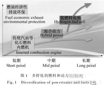
A fuel cell vehicle is a type of electric vehicle. The electricity generated by the fuel cell is supplied to the motor through the inverter, controller, etc., and then the wheel is rotated by the transmission system, the drive axle, etc., so that the vehicle can travel on the road, and the energy conversion efficiency of the fuel cell is higher than that of the internal combustion engine. 2-3 times. The chemical reaction process of a fuel cell does not produce harmful products, so the fuel cell vehicle is a pollution-free car [1-3]. With the requirements of automobile fuel economy and environmental protection, the automotive power system will gradually transition from hybrid gas to gasoline and other hybrid fuels, and will eventually be completely replaced by clean fuel cell vehicles [4].
In recent years, significant progress has been made in fuel cell systems and fuel cell vehicle technology [4-5]. World-renowned automakers such as Toyota, Honda, GM, DaimlerChrysler, Nissan and Ford Motor Company have developed several generations of fuel cell vehicles [5-12] and announced various fuel cell vehicles for the market. strategy
aims. At present, prototypes of fuel cell cars are being tested, and fuel cell-powered transportation buses are undergoing demonstration projects in several cities in North America. Among them, Honda's FCX Clarity has a top speed of 160 km/h [8]; Toyota fuel cell vehicle FCHV-adv has already run a 360,000 km road test, which can start at minus 37 degrees, and one hydrogenation can travel from Osaka to Tokyo. (560 km) [7]. With the support of the Ministry of Science and Technology of China, fuel cell vehicle technology has developed rapidly. In 2007, China's fourth-generation fuel cell car was successfully developed. The car has a top speed of 150 km/h and a maximum driving range of 319 km. In 2008, 20 fuel cell demonstration vehicles were demonstrated in the Beijing Olympics. In 2010, a total of 196 fuel cell vehicles, including SAIC and Chery, were demonstrated in the Shanghai World Expo Park [13].
There are still technical challenges in the development of fuel cell vehicles, such as the integration of fuel cell stacks, the improvement of commercial electric vehicle fuel processors and auxiliary automobile manufacturers are working towards integrating components and reducing component costs. Significant progress has been made. However, compared with traditional internal combustion engine cars, fuel cell electric vehicles use "fuel cells + electric motors" to replace the "heart" of the traditional car - the engine and fuel system. The powertrain of the fuel cell car has undergone major changes, mainly in the following: the electric motor replaces the internal combustion engine as the driving power source; the clutch and torsional vibration damper are omitted; the multi-speed transmission is usually replaced by the speed reducer [14, 15]. Therefore, the powertrain of a fuel cell vehicle is generally simplified. However, when driving, the fuel cell is the main source of power, and the battery is the source of auxiliary energy. The power required by the car is mainly provided by the fuel cell. It can be said that the selection of fuel cells for vehicles is crucial for the performance of fuel cell vehicles.
This paper introduces the development of traditional technology of fuel cell vehicle power, and discusses the key technologies such as fuel cell electric vehicle power transmission topology, multi-source system management and power system configuration and simulation optimization technology.
2 Powertrain topology design
The operation of fuel cell vehicles is not a steady state situation. Frequent start-up, acceleration and hill climbing make the dynamic conditions of the car very complicated. The dynamic response of the fuel cell system is relatively slow, and the output characteristics of the fuel cell cannot meet the driving requirements of the vehicle during start-up, rapid acceleration or steep climb. In actual fuel cell vehicles, it is often necessary to use a fuel cell hybrid electric vehicle design method, that is, to introduce an auxiliary energy device (battery, supercapacitor or battery ten supercapacitor) through a power electronic device and a fuel cell in parallel to provide peak power. Complement the lack of fuel cell output power capability when accelerating or climbing a vehicle. On the other hand, in the case of automobile idle speed, low speed or deceleration, when the power of the fuel cell is greater than the driving power, the surplus energy is stored, or when the feedback brake is applied, the stored braking energy is absorbed, thereby increasing the energy of the entire power system. effectiveness.
2.1 Direct fuel cell hybrid system structure
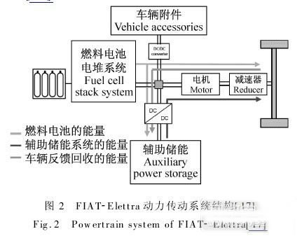
The power electronic device used in the direct fuel cell hybrid system structure has only a motor controller, and the fuel cell and the auxiliary power device are directly connected to the inlet of the motor controller. Such a similar structural design is adopted for Toyota's FCHV-4 [16], FIAT-Elettra [17] and Nissan X-Trail FCV [12].
The auxiliary power unit expands the total energy capacity of the power system, increases the driving range of the vehicle after one hydrogenation, expands the power range of the system, and reduces the power load of the fuel cell. Many plug-in hybrid fuel cell vehicles often use such a structure, the US Ford Edge Plug-in fuel cell car and the GM Volt Plug-in fuel cell vehicle [18]. This plug-in hybrid vehicle will effectively reduce the consumption of hydrogen fuel. In addition, the presence of the auxiliary power unit provides the system with the ability to recover braking energy and increases the reliability of system operation. A reasonable distribution of load power between the fuel cell and the auxiliary power unit can also improve the overall operating efficiency of the fuel cell [4].
In the system design, a bidirectional DC/DC converter can be added between the auxiliary power unit and the power system DC bus. The control of charging and discharging the auxiliary power unit is made more flexible and easy to implement. Since the bidirectional DC/DC converter can better control the voltage or current of the auxiliary power unit, it is also an executing component of the system control strategy.
2.2 Parallel power system structure
Another architecture is the structure of a parallel fuel cell hybrid system. This construction typically involves the installation of a DC/DC converter between the fuel cell and the motor controller. The terminal voltage of the fuel cell is matched to the voltage level of the system's DC bus by boosting or stepping down the DC/DC converter. This system differs from the above-mentioned architecture in that the design of the power system does not take into account the energy recovery and recovery, so the system is simple, but the efficiency is relatively low.
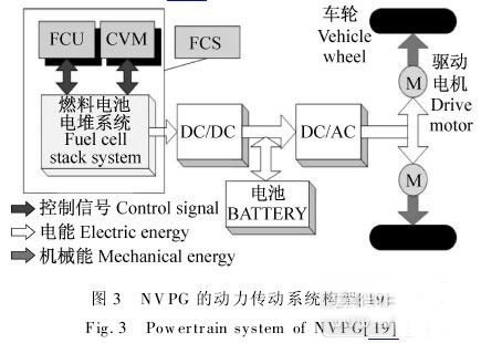
Although there is no longer a coupling relationship between the voltage of the system DC bus and the fuel cell power output capability, the DC/DC converter must maintain the voltage of the system DC bus at the voltage point (or range) optimal for the operation of the motor system. For motor drive systems, a DC/AC converter is usually required. At present, such frame systems are only used in some small or experimental cars. For example, the Autonomy and Hy-wire cars developed by General Motors in 2002 are based on the structure [10]. In 2008, the Tongji University-ThyssenKrupp Joint Laboratory developed a small fuel cell vehicle using this architecture [19] and studied the impact of the fuel cell stack system on overall vehicle performance.
3 Fuel cell vehicle multi-energy system management and optimization
Fuel cells are not suitable as a single driving energy source for power systems. The auxiliary energy system must be used to properly supplement the energy required to drive electric vehicles, cover power fluctuations, increase peak power, absorb feedback energy, and improve transient characteristics of fuel cell output power. At present, major car developers have adopted auxiliary power to improve the performance of fuel cell vehicles (Table 1).
3.1 Power Battery Auxiliary Energy System
At present, lead-acid batteries [20] have been eliminated due to their lower specific energy and specific power. The main power batteries used in automobiles are nickel-metal hydride batteries and lithium-ion batteries.
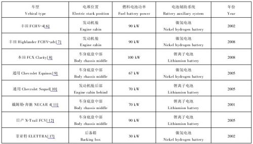
Table 1 Typical fuel cell vehicle
Table 1 Typical fuel cell electric vehicles
Nickel-metal hydride batteries are alkaline batteries, which have the advantages of being less prone to aging, requiring no pre-charging, and good low-temperature discharge characteristics. Its energy density can exceed 80 Wh/kg, and the driving distance on one charge is long, and it can discharge smoothly during high current operation. The power systems of FCHV-4 [6], High-lander FCHV-adv [7] and GM Chevrolet Equinox [9] are all integrated with fuel cells and nickel-metal hydride batteries. However, in the high temperature environment, nickel-metal hydride has a sharp drop in battery charge, and has problems in memory effect and charging and heating. In the fuel cell hybrid system, the NOx of the NiMH battery should be kept between 40% and 60%. The charge and discharge current should be in the range of 160-240 A. The temperature should be maintained near normal temperature to ensure system safety and economy. 21, 22].
Lithium-ion batteries have the advantages of small volume, high energy density (>120Wh/kg), high safety and no pollution. Honda FCXClarity [8], General Chevrolet Sequel [10] Lithium and Nissan X-Trail FCV [12] use lithium-ion batteries as an auxiliary energy system for fuel cell vehicles. The energy density of an ion battery is 1.5-3 times that of a nickel-hydrogen battery. The average voltage of the single cell is 3.2V, which is equivalent to the voltage value of three nickel-zinc or nickel-hydrogen batteries connected in series, thereby reducing the number of battery assemblies and reducing the probability of battery failure caused by the voltage difference of the single cells. , thereby increasing the life of the battery pack.
Lithium-ion batteries have the advantage of low self-discharge (only 5%-10%). When stored in non-use state, the interior is quite stable and almost no chemical reaction occurs [4, 5]. Since lithium-ion batteries do not contain heavy metals such as cadmium, mercury, and lead, they do not pollute the environment during use. For electric vehicles, lithium-ion batteries are easy to install and install in the vehicle, which is an ideal energy storage medium. Tools such as Simulink and Dymola are often used to simulate the battery system [23] to improve battery efficiency and longevity.
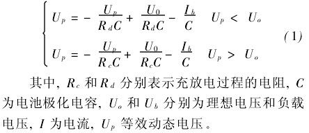
The dynamic process of charge and discharge can be used with the Thevenin model as follows [23, 24]:
3.2 Super Capacitor System
Supercapacitor is a new type of energy storage component that has high discharge power like electrostatic capacitance and large charge storage capacity like a battery [23, 25]. Because its discharge characteristics are closer to electrostatic capacitance, it is still called "capacitance".
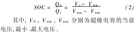
If only supercapacitor is used as the only auxiliary energy source, there are still many shortcomings, such as: the electric vehicle starts again after a long shutdown, due to the self-discharge effect of the super capacitor, the power supply of the vehicle auxiliary system will not be stabilized when the energy output of the fuel cell is not stabilized. Unable to guarantee [5]. Moreover, the energy density of the supercapacitor is very low, and the device volume is bound to increase if a certain energy reserve capacity is to be achieved. Current supercapacitors are used in conjunction with other power batteries to purchase auxiliary power systems for use in fuel cell vehicles [4, 25, 26]. In order to overcome the precise description of the characteristics of the supercapacitor, the impedance method can be used to model the simple RC loop model [23]. Super Capacitor The current SOC is based primarily on the output voltage of the supercapacitor:
3.3 Combination and control of multiple source energy
Fuel cell electric vehicles are equipped with the above two topologies, combined with power batteries and super capacitors to achieve better results. At present, the three main energy combinations are: 1) fuel cell + power battery, universal Chevrolet Equinox, etc. [9,10,12]; 2) fuel cell + super capacitor, such as Honda's FCV -3 and Mazda FC-EV, etc. [4]; 3) Fuel cell + power battery + super capacitor, such as Honda FCHV-4 [8]. Tadaichi [6] studied the way energy flows in different situations. Based on the comparison of three kinds of energy sources for vehicles, a multi-energy energy management system was designed based on the fuel cell engine output power prediction control strategy, and optimized management and control of three kinds of energy sources were realized [26].
4 Power System Configuration and Simulation Optimization Technology
4.1 Fuel cell system simulation technology
The method of modeling the fuel cell system in a fuel cell vehicle can be divided into two types. One is to establish a relatively complex one-dimensional or multi-dimensional physical model based on the theory of electrochemistry, engineering thermodynamics, and fluid mechanics [27]. . This model can establish corresponding models according to the structural parameters of different fuel cells, and analyze the effects of various factors such as pressure, temperature, humidity, flow, catalyst, and pipeline structure on the fuel cell operation. However, this model is complex and not intuitive, and the operation speed is slow. The other uses a simpler mathematical experience model combined with the corresponding commercial software [24, 26], which is intuitive and fast, but the model can only be targeted to specific fuel cell systems, and its establishment depends on experimental data. .
4.2 Simulation and optimization technology of vehicle power transmission system
The ultimate goal of fuel cell vehicle simulation is based on the fuel cell model, combined with the relevant models of the subsystem and power transmission system, simulation analysis of the fuel cell system and even the entire automotive power system. This method of system optimization is mainly carried out in combination with actual use, and is generally divided into two types [24, 27].
In the case where the actual road conditions are unknown, T. Gabriel Choi et al. [28] of Ohio State University based on the FIAT Panda model, studied the control requirements of the fuel cell plug-in electric vehicle: offline global optimization and dynamic optimization The setting method of the lower control measurement. Energy optimized control method for home charging and fuel cell hybrid applications. Guezennec et al. [29,30] studied the use of energy by driving habits and optimized the powertrain and size capacity.
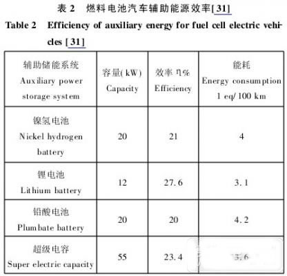
For the actual use situation, Xie Changjun et al [26] studied the optimization method under the conditions of cruise acceleration, etc., Francisco et al. [31] studied the design of the fuel system electric vehicle power system capacity under the rural route, urban route and the mixture of the two. In this paper, the efficiency and energy consumption of the power system under different auxiliary energy systems are studied, which provides a reference for the design of fuel cell power system. Keshav S et al. [32] used the Power System Simulation Analysis Tool (PSAT) to analyze the performance of fuel cell vehicle systems including fuel cell stacks and other components, and found that lithium batteries work best when using a single auxiliary energy (Table 2). ). When lithium batteries and super capacitors are mixed, they can be 9% efficient. In addition, further consideration is needed for the mechanical structure of the fuel cell and its dynamics [14].
5 Summary
The fuel cell stack in a fuel cell electric vehicle can only maintain the average power requirement of the vehicle operation, and the auxiliary energy system improves the efficiency of the fuel cell vehicle. Focusing on the key technologies of fuel cell vehicle power traditional technology, this paper discusses the key technologies of fuel cell electric vehicle power transmission topology, multi-source system management and power system configuration and simulation optimization technology. The research in this paper has important reference value for the traditional design and manufacture of fuel cell electric vehicle power.
3020 White SMD LED is deeply loved by their users because of the small size, the high brightness.
It is often used in LED lighting, LED Lamps, LED backlight, LED panel lights, LED furniture, landscape LED, LED Lighting, LED Lighting, led Backlight, LED Panel Light, LED Furniture, LED Photo Light, LED Aperture, LED Toys, grow light LED, fill light LED, LED aperture and other lighting products.
White SMD LED, it is the light produced by the blue color chip which is transformed by the special LED fluorescent powder. It does not have a fixed wavelength range and value, which meas White LED need the coordinate value of X, Y and color temperature to represent it. In 18 years, we supply the white SMD LED with high efficiency, high luminance, low light attenuation has been recognized by our customers.
We supply kinds of 3020 Smd LED with different wavelength from 365nm to 1550nm, which include the visible LED and the invisible LED.
In this catalog, we mainly introduce the 3020 white SMD LED of visible light. 3020 SMD LED, size is 3.0*1.4mm. For this white SMD LED, we can package with single chip 3020 SMD LED or 2 chips 3020 SMD LED and the power can be 0.06W 3020 white SMD LED, 0.1W 3020 white SMD LED, 0.2W 3020 white SMD LED, 0.5W 3020 white SMD LED and so on.
The white SMD LED's voltage is 2.8-3.5V.
We have a variety of color temperature to select from. For instance: White 3020 SMD LED with 2700K,White 3020 SMD LED with 2800K,White 3020 SMD LED with 2900K,White 3020 SMD LED with 3000K,White 3020 SMD LED with 3200K,White 3020 SMD LED with 500K,White 3020 SMD LED with 4000K,White 3020 SMD LED with 4500K,White 3020 SMD LED with 5000K,White 3020 SMD LED with 5500K,White 3020 SMD LED with 6000K,White 3020 SMD LED with 6500K,White 3020 SMD LED with 7000K,White 3020 SMD LED with 7500K,White 3020 SMD LED with 8000K,White 3020 SMD LED with 9000K,White 3020 SMD LED with 10000K,White 3020 SMD LED with 15000K,White 3020 SMD LED with 20000K,White 3020 SMD LED with 30000K ect.
3020 White SMD LED
3020 White SMD LED, Soft White SMD LED, White LED 3020 SMD, White LED 3020 SMD
Shenzhen Best LED Opto-electronic Co.,Ltd , https://www.bestsmd.com