Overvoltage Generation and Regenerative Braking
Overvoltage in an inverter occurs when the DC bus voltage exceeds its rated value, typically due to various operational conditions. Normally, the DC voltage is derived from three-phase full-wave rectification of the input line voltage. For a 380V supply, the average DC voltage (Ud) is approximately 1.35 × 380 = 513V. However, during certain situations, this voltage can rise significantly, reaching up to around 700V, triggering the inverter's overvoltage protection.
There are two primary causes of overvoltage: supply overvoltage and regenerative overvoltage. Supply overvoltage occurs when the input voltage exceeds the inverter’s allowable range, but modern inverters are generally designed to handle voltages up to 460V, making this scenario rare. The more common issue is regenerative overvoltage, which arises when a motor operates in a generating mode.
Regenerative overvoltage typically happens when a system with high inertia—such as a large GD² load—decelerates too quickly. In such cases, the motor may spin faster than the commanded speed, either due to external forces or potential energy loads like elevators or cranes. This results in negative slip, where the rotor moves faster than the magnetic field, causing the motor to act as a generator. The kinetic energy from the load is then converted into electrical energy, which is fed back into the DC bus through the inverter’s freewheeling diode.
This regenerated energy charges the DC bus capacitor, increasing the voltage and potentially triggering overvoltage protection. This process is known as regenerative braking, as it generates a braking torque that opposes the motion. While the inverter and motor can initially absorb up to 20% of this energy, excessive regenerative power can overload the system, leading to shutdowns if not properly managed.
To prevent overvoltage, several strategies can be employed. If parking time or position is not critical, extending the deceleration time or using free stop (where the inverter disconnects and the motor coasts to a halt) can help. For applications requiring controlled stopping, DC braking can be used. This involves applying DC current to the stator windings to create a static magnetic field, inducing braking torque in the rotor. Although effective for short stops, DC braking is inefficient and can cause motor overheating if used for extended periods.
For deceleration without full stop, adjusting the deceleration time can reduce overvoltage caused by high GD² loads. This approach leverages the inverter’s built-in regenerative capacity. However, for continuous regeneration due to external forces or potential energy, more advanced solutions are needed.
Regenerative braking is the most efficient method, offering higher braking torque and automatic control based on the level of regenerative energy. It is ideal for normal operation, where consistent braking is required.
Regenerative Braking Methods:
1. Energy Dissipation Type:
In this method, a braking resistor is connected in parallel with the inverter’s DC link. A power transistor is activated when the DC voltage reaches a set threshold (around 700V), directing the excess energy to the resistor for dissipation as heat. This prevents overvoltage while protecting the inverter. Unlike DC braking, this method does not overheat the motor, allowing for more frequent operation. It is a reliable solution for managing regenerative energy in industrial applications.
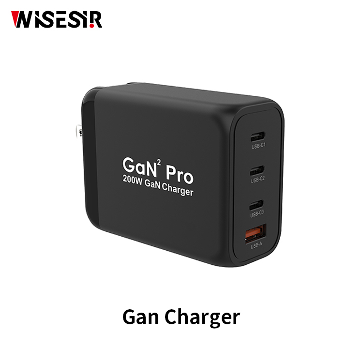
Gan chargre
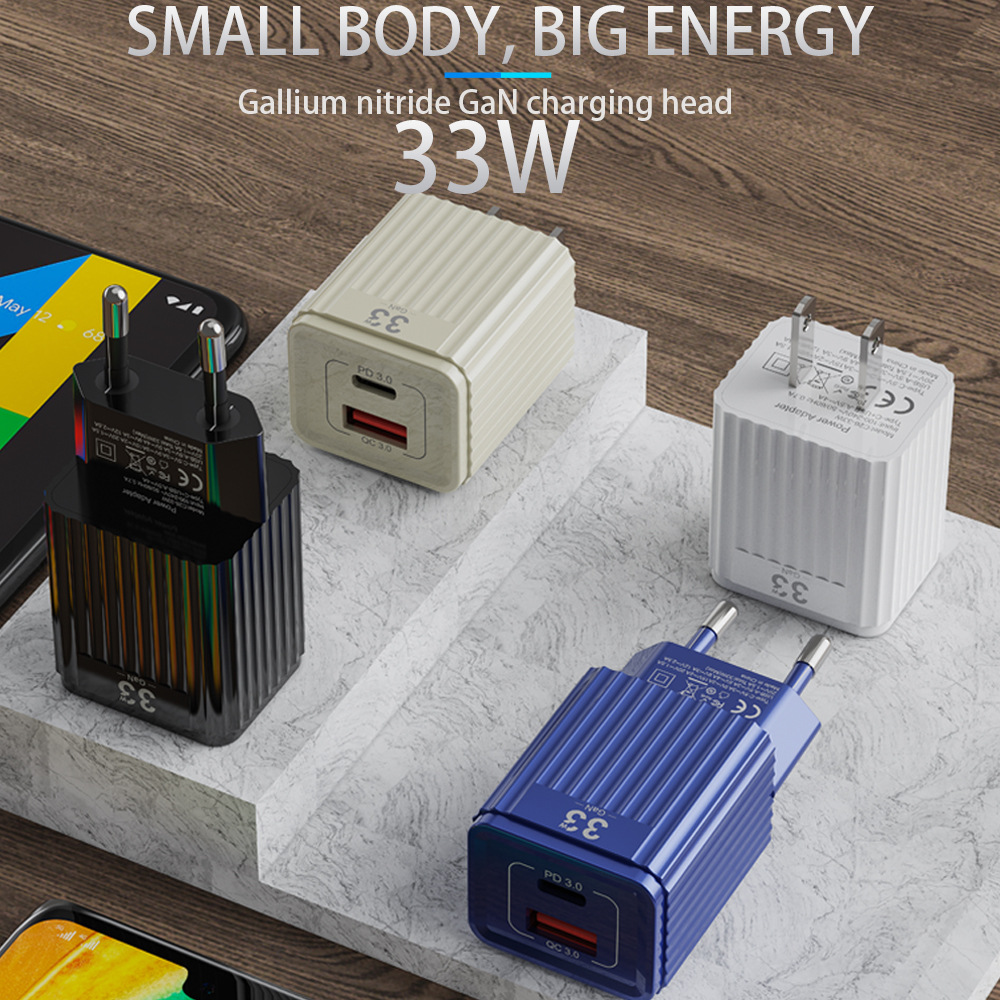
Gallium nitride, or GaN, is a material that's starting to be used for semiconductors in chargers.The main thing about GaN when it comes to chargers is that it produces less heat.Ultimately, this means your devices will charge faster with a GaN charger than with a silicon one. In summation, GaN chargers are more power efficient, significantly smaller, and capable of charging your devices much faster than a silicon-based charger.


Gan Fast Charger,Best Gan Charger,Baseus Gan Charger,Anker Gan Charger,Usb to Usb Charger
Pogo Technology International Ltd , https://www.wisesir.net
