At present, multi-channel illumination LEDs are being widely used, but each LED is equipped with a separate driving source, and experimental research has been conducted in order to control the cooperation of multiple LEDs. The method used in the experiment is: the computer sends a dimming signal to the single-chip microcomputer, and the CD4067 is used for multi-path selection in the dimming circuit, and the single-chip microcomputer generates PWM to adjust the current value, wherein the dimming circuit adopts a mediation working current mode and a pulse width modulation mode. Ways. Through experimental research, the principle of multi-channel dimming control is expounded, the feasibility of two dimming methods is demonstrated, and the input-output relationship of the whole circuit is obtained, so that the brightness of multiple LEDs can be specifically controlled.
1 Introduction
Lighting technology has experienced three important development stages over the past 100 years: incandescent, fluorescent and HID lamps. Due to many advantages such as environmental protection, long life and high photoelectric efficiency, LED has been rapidly developed in various industries in recent years. The illuminating characteristics of white LEDs have such characteristics: the luminous intensity of white LEDs is determined by the driving current. When the voltage across the LED fluctuates, the current flowing through the LED changes greatly, and the luminous intensity of the LED is proportional to the driving current, so the driving current directly affects the LED's luminous quality.
Lighting LEDs in many places are multi-channel LEDs to work together, and in order to achieve energy saving and dimming to eliminate shadows, multi-channel LEDs need to be dimmed. The article gives a way to control multi-channel dimming. method.
2 The design idea of ​​the whole system
Figure 1 is the design framework of the whole system. The computer sends the dimming signal through the serial port communication. After receiving the signal, the MCU generates the control signal and sends it to the dimming circuit through internal calculation. The dimming circuit then sends the driving signal to the multi-channel. Illumination LEDs enable computer-controlled multi-channel LED brightness adjustment. Among them, the design of multi-channel dimming circuit is the key of this chapter. Multi-channel dimming uses C language programming, first simulate in Proteus, and then build the actual circuit.
Figure 1 system frame diagram
3 multi-channel dimming circuit design
3.1 Multi-channel control design
Multiple control method: The multi-channel control is realized by the sixteen-one analog Switch CD4067. The pins of CD4067 are shown in Figure 2. When it is necessary to adjust a branch, it is only necessary to strobe this branch for adjustment. At this time, other branches are not affected. Two CD4067s were used in the test, one as the transmission path for controlling each branch and the other as the transmission path for the feedback signal. Both switches simultaneously strobe a branch and can only strobe that way.
3.2 Dimming circuit design
Since the brightness of the LED is proportional to the forward current, the current is adjusted to change the brightness. There are two ways to adjust the brightness of the LED by adjusting the current: (1) Adjust the operating current mode. (2) Pulse width modulation (PWM) mode.
3.2.1 Method of adjusting working current
Figure 2 Multiple control flow for adjusting the operating current mode
As shown in Figure 2, the MCU sends the PWM signal to the CD4067, which is selected by the MCU. The CD4067 responds to the signal from the MCU, strobes the corresponding branch, and generates a voltage as a FET through the RC integration circuit. The gate voltage of 2SK1058, because the current of FET 2 SK 1 0 5 8 is controlled by the gate voltage, the current of the LED is controlled by the PWM signal generated by the microcontroller. In order to achieve stable output, a feedback circuit is added to the circuit. The given value of this feedback circuit is the given voltage value generated by the microcontroller to control the digital-to-analog converter.
3.2.2 Pulse Width Modulation
Pulse Width Modulation (PWM) mode: quickly switches the LEDs at frequencies that are not easily noticeable by the human eye, giving the impression that the LEDs are always bright. The switching time ratio determines the average current flowing through the LED, which determines its brightness. The main difference between the pulse width modulation mode and the regulation of the operating current mode is that instead of using the RC integration circuit, the IFR830 is used instead of the 2SK1028. By quickly controlling the on and off of the IFR830, the LED current is a pulse current with a constant amplitude and a fast frequency. The average current of the LED determines the brightness of the LED. The control flow is shown in Figure 3.
Figure 3 Multi-channel control flow in pulse width modulation
4 Experimental analysis
Since two dimming methods are employed, the experimental scheme is performed in accordance with multi-channel control based on two dimming methods.
4.1 Multi-channel control based on regulating operating current mode
Since the CD4067 chip can drive sixteen branches, the representative three branches are controlled during the experiment. By setting the current values ​​of the three branches, the three branches are brought to their respective brightnesses. However, since the relationship between the LED current value and the input value of the DAC0832 is unknown, experiments are performed to obtain the relationship between them, and then the communication interface can be programmed so that the input value of the computer interface can correspond to the LED current.
Figure 4 driving waveform
On the computer operation interface, the input of the first channel DAC0832 is 100, the second channel is 200, the third channel current value is 255, and the current value of the corresponding branch LED is measured to be 54mA, 106mA, 134mA, corresponding to 2SK1058 The drive waveforms are shown in Figure 4.
It can be seen that as the input of the DAC0832 increases, the duty cycle of the PWM becomes larger and larger, and the corresponding LED current value also increases. In order to get the relationship between them, test the input and key voltage values ​​of multiple DAC0832 by changing the program method (taking into account the non-linear region between 0 and 100, so the value starts from 100), measured The data is shown in Table 1.
Table 1 Measurements of NI data
Draw an approximate relationship between N and I, as shown in Figure 5. As can be seen from the figure, the input of the DAC0832 and the LED current value are basically proportional to each other, and the relationship between them can be approximated: Y=0.53X+1.09, where Y represents the current value of the LED in mA. X represents the input of the DAC0832. According to this relationship, we can set the program so that the input value on the computer interface is converted to the corresponding DAC0832 value, so that the LED current can be controlled and the LED light can be adjusted over a wide range. brightness.
Figure 5 NI curve
4.2 Multi-channel control based on pulse width modulation
Similarly, considering that the CD4067 is a sixteen-choice switch, it is not necessary to control the sixteen channels. It is proposed to use three branches to represent the control process of the entire circuit. Because of the different control methods, it is determined that the brightness of the LED is different. The method based on pulse control determines the brightness by the average current of the LED. By programming, the frequency of the PWM wave is set to 1KHZ, the duty ratio of the first path is 0.2, the second path is 0.4, and the current value of the third path is 0.6, which is measured by measuring the 5 ohm resistor in series with the LED. With the voltage, the current waveform of the LED can be obtained, so that the average current of the LED can be seen. The waveforms are shown in Figure 6:
Figure 6 Drive waveform and current-limiting resistor voltage waveform
In the figure, 1 channel is the PWM waveform, and 2 channels are the 5 ohm resistor voltage waveform. It can be seen that the LED current amplitude IM is 0.65/5=130mA is constant, and the duty ratio of the LED current and the PWM drive waveform The duty cycle is the same, so the formula is obtained: LED average current I= D*IM, where IM=130mA. Therefore, it can be transmitted to the MCU signal by setting the duty cycle on the computer operation interface. The brightness of the LED.
4.3 Comparison of the two methods
Through these two methods, multi-channel control can be realized, and the experimental purpose can be achieved. The difference is that the input control amounts of the two methods are different. However, it can be found through many experiments that in the process of constant regulation, the former circuit The LED current has a color decay phenomenon, while the LED still emits white light corresponding to the current, so the second method can be widely used.
5 Conclusion
In this test, the computer operation interface is used to control the dimming circuit and the single-chip output PWM method. Combined with the chip CD4067, the control of the multi-channel LED current value is realized. Two dimming methods are adopted. According to this conclusion, it can be applied to many occasions where multiple LEDs are controlled, such as surgical lights, home lighting, and large outdoor lighting design.
Of course, the MCU combined with the CD4067 can control multiple LED currents, but there are also some shortcomings and areas for improvement. Since the multi-channel illumination LEDs work more powerfully, some components can be added to the circuit of this paper to reduce The purpose of loss; because there is no reference voltage pulse amplitude, the PWM wave directly generated by the microcontroller is not very constant, which limits the range of use of the PWM wave.
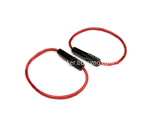
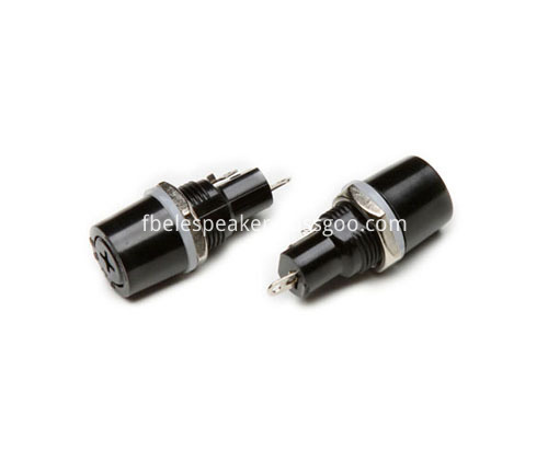
Fuse Holder can be divided into: panel mounting Fuse holder, PCB mounting fuse holder, lead wire fuse holder and automobile fuse holder;The panel is equipped with fuse holder (mostly used for electric equipment, such as power amplifier, DVD, Speaker, massage chair, etc.);Lead fuse holder (used for connecting small electrical appliances and industrial mechanical wire harness);PCB fuse holder (mostly used in small appliances control panel) and fuse holder (mostly used in small appliances control panel).Automobile fuse holder can be divided into lead wire fuse holder (multi-purpose automobile and industrial machinery wire harness);The panel is equipped with a car fuse holder (usually used for automotive appliances, such as power amplifier, refrigerator, DVD, etc.) and a car fuse holder.The fuse holder has the requirements of current resistance, voltage resistance and fire protection level, and generally needs to pass UL CSA VDE ROHS safety regulations and eu certification.


Fuse Holder
Fuse Holder,Plug-In Fuse Holder,Fuse Box Holder,Middle Type Fuse Holder
Ningbo Best Group Co.,Ltd , http://www.speakerbuzzer.com
