
The motor energy feedback problem is a common problem that occurs in motor drive systems. Many designers have to choose a motor supply voltage (VM) rating that is equivalent to twice the rated voltage level, which increases system cost. Fortunately, if you can estimate the pumping range first, you can choose the right VM margin. In the first article in this series (specially for frequently asked questions), Nicholas Oborny provided advice on how to read the motor drive product specification. Today, by introducing a method for estimating pump lift levels, the author will continue to talk about this topic.
VM pump up waveform
Figure 1 shows a typical VM pumping waveform caused by energy feedback during deceleration. When the input PWM (Pulse Width Modulation) duty cycle is changed from 99% to 70%, the VM voltage is pumped from 24V to 32V. (The DRV8840 is a 5A brushed DC (DC) motor driver tested on the TI motor driver unit DRV8840.)
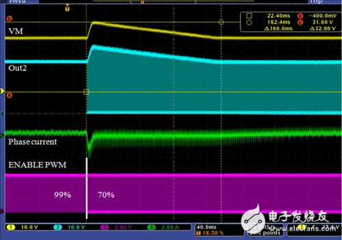
Figure 1: Regeneration of electric energy and VM pumping
Pumping mechanism
Here we need some DC/DC power management background information to understand the pumping mechanism. So let's take a look at how a typical buck-boost circuit works; see Figure 2. Interestingly, when using an H-bridge to drive a motor during PWM control, you can see both the buck and boost processes. As shown in Figure 3, it is a typical step-down circuit during the PWM turn-on period. In FIG. 4, during the off period of the PWM, for the back electromotive force (EMF), it acts as an input power source in the boosting mechanism.
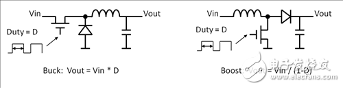
Figure 2: Buck and boost circuits
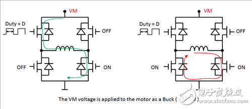
Figure 3: Bucking in the H-bridge
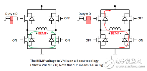
Figure 4: Boost conversion in the H-bridge
The operating mode of the brushed DC motor can be expressed as equation (1).
Under normal drive conditions, the PWM duty cycle = D, the motor will operate at the speed driven by the voltage VDRV as shown in equation (2).
According to equation (1), we should be able to estimate
The boost effect will make VBST
According to equations (2), (3), (4), we can estimate
Therefore, there is no VM pump lift in normal operation.
When the PWM duty cycle is reduced from D1 to D2, we can estimate it before the time point at which the decrease occurs.
After the duty cycle has just decreased, the speed of the motor cannot be changed abruptly, so the VBST is calculated based on the new duty cycle D2.
According to equations (6) and (7), we can
When K * D1/ D2 > 1, we can estimate
VBST will be higher than VVM and cause a pumping effect. Assuming K is close to 1, then whenever you decrease the duty cycle and D2 < D1, the VM pump rises. For example, if you reduce the duty cycle from 100% to 50%, then VBST = 2 * VM. If you reduce the duty cycle from 90% to 30%, you will see that the pump voltage is three times that of the VM.
Pump test
Blood Pressure Monitor,Blood Pressure Machine,Blood Pressure Checker,Digital Blood Pressure Monitor
GANSU PINGLINAG ABAY SCIENCE&TECHNOLOGY CO.,LTD , https://www.yzwtech.com