
RFID security certification based on TH-PPM
0 Introduction In recent years, many RFID security authentication algorithms and protocols (such as Hash-Lock protocol, packet encryption algorithm) solve the security authentication of RFID systems at the protocol layer and algorithm layer, and these methods all assume between the tag and the reader The communication has been eavesdropped to achieve the protection of information. Digital encryption algorithm will inevitably increase the complexity of the tag circuit and thus increase the power consumption of the tag. Research shows that the AES algorithm composed of 3 595 NAND gates requires 8.5 μA current to drive, even if the power consumption and cost of the encryption algorithm are reduced, the encryption algorithm The delay can not be ignored, because the encryption algorithm requires multiple cycle counts, and works under a low-frequency clock, so that most of the communication between the tag and the reader is wasted on implementing encryption. Research has proved that it takes about 995 cycles to implement an AES algorithm. Assuming that the clock of the tag is 1 MHz, it takes about 1 μs to complete AES encryption, while the Gen-2 standard tag has only 1.6 μs to transmit 128-bit information. Visible encryption The delay of the algorithm is considerable.
In order to solve the shortcomings of digital encryption, people have proposed a variety of lightweight security certifications (such as HB, HB +, HB ++ protocols) in an attempt to reduce the cost and power consumption of tags. In the HB protocol, the tag and the reader share a key x. The flow of the HB protocol is: a random challenge value a generated by the reader and sent to the tag; the tag passes a series of calculations according to the values ​​of a and x. The result is sent to the reader; the reader checks whether the result meets the specifications; if the reader fails to verify the result sent by the tag within the specified number of times, the tag passes the verification. Although the HB protocol simplifies the circuit structure, it cannot resist active attacks. If the attacker pretends to be a reader and sends a modified random challenge value a to the label n times, the value of x can be guessed.
Due to the shortcomings of the HB protocol, many scholars have produced HB + protocol and HB ++ protocol for their improvement, and also produced some new protocols (such as Hash-Lock and Hash chain protocol), but they are all based on Hash operation module or block encryption algorithm. It does not reduce the cost and power consumption of label safety certification.
Due to the above defects of the encryption algorithm, UWB-based RFID security authentication is proposed. This authentication is to protect the data of the RFID system on the physical layer of communication and adopts TH-PPM modulation. Each tag of the TH-PPM modulation and demodulation system uses its own specific time-hopping code, and only a receiver that knows the time-hopping code can demodulate the signal. The advantages of UWB-based RFID security certification are:
(1) The power of the UWB signal is close to the noise power of the channel, and it is difficult to be eavesdropped;
(2) UWB signals do not need to be encrypted, because each tag has a different time-hopping code, and the time-hopping code is absolutely confidential;
(3) Because the UWB-based RFID security authentication system does not have the delay of the encryption algorithm, the communication delay is shorter; the UWB signal has better anti-interference performance than the narrowband signal, it is not easy to block and eavesdrop, and frequency reuse can be achieved.
l UWB RFID security certification system
1.1 UWB and TH-PPM
According to Shannon's law, under the condition of noise interference, the limit transmission rate (channel capacity) of a communication system can be expressed by Shannon's formula, namely: C = Blog (1 + SNR) (C is the channel capacity; B is the signal bandwidth; SNR Is the signal-to-noise ratio). According to Shannon's formula, under the condition that the channel capacity is constant, the signal-to-noise ratio and the signal bandwidth can be replaced with each other, so when the signal-to-noise ratio is constant, the channel capacity is proportional to the bandwidth, and increasing the bandwidth increases the channel capacity (limit Within the capacity), while reducing the requirements for the signal-to-noise ratio, broadband communication systems such as spread spectrum and ultra-wideband are derived from this.
UWB signal refers to its relative bandwidth is greater than 0.2, it uses a very narrow pulse (pulse width is generally less than 1 ns) to transmit data, rather than using a continuous waveform, so the bandwidth of the signal is large. Narrow pulses generally use Gaussian multi-order differential pulses, raised cosine pulses, multi-period pulses, and pulse trains. Because Gaussian multi-order differential pulses are easy to generate and the order is selected properly, the signal has no DC component and can Radiant energy in the air (such as first-order, second-order differential, etc.), so it is most commonly used. The mathematical expression of Gaussian multi-order differential is: 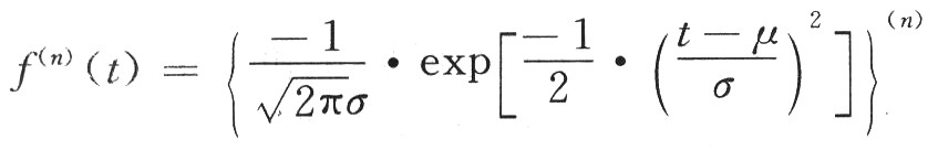
UWB system has a variety of pulse modulation methods (TH-PPM, DS-PAM, etc.), because TH-PPM circuit is simple, low cost and low power consumption, so it can be used for the modulation method of UWB RFID system. PPM modulation uses the deviation of the position where the pulse appears from the standard position to represent a specific symbol. TH-PPM is a combination of time hopping and pulse position modulation. First, the PN code is used to select the time slot of the transmission symbol (the time hopping of a PN code with a period of 2N-1, due to the pseudo-random generator within one cycle of the PN code There are 2N-1 states, so it takes 2N-1 time slots to transmit a symbol); then use the symbol to control the pulse's offset from the standard position in the selected time slot in PPM modulation, the TH-PPM signal is : 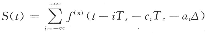
For example, for a binary source, when hopping with a PN code with a period of 2N-1, first select the time slot for transmission of the PN code according to the state cj of the PN code generator, that is, shift ciTc in the bit space; then, when selecting In the slot, when the symbol is "0", the position of the pulse does not shift. When the symbol is "1", the position of the pulse in the time slot is shifted by ai △, and the total offset of the pulse in the bit space is ciTc + ai △, request ai △ "ciTc (when ci ≠0).
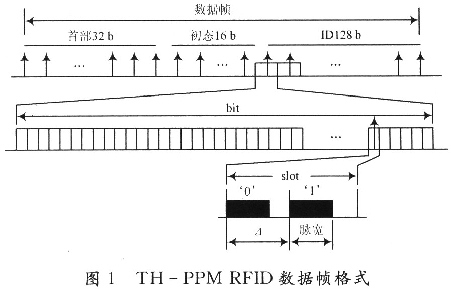
1.2 TH-PPM RFID data frame structure The data frame format of TH-PPM RFID is shown in Figure 1. The bottom layer of the figure is a time slot in the bit space where the transmission symbol is randomly selected. From the above analysis, there can only be one bit space There are only pulses in the time slot, and different offsets in a time slot represent different symbols. It can be seen from the figure that the entire data frame has a total of 176 b and is divided into three parts: the header, the initial state of the PN sequence, and the tag ID. The header consists of 32 b, which is used for the synchronization of tags and readers. The initial state and tag ID of the PN sequence are composed of 16 b and 128 b, respectively. The initial state of the PN sequence is transmitted to the reader to achieve pseudo-random code synchronization. If the PN code is not synchronized, the reader cannot despread the signal and cannot obtain label information, so synchronization is the key to TH-PPM.
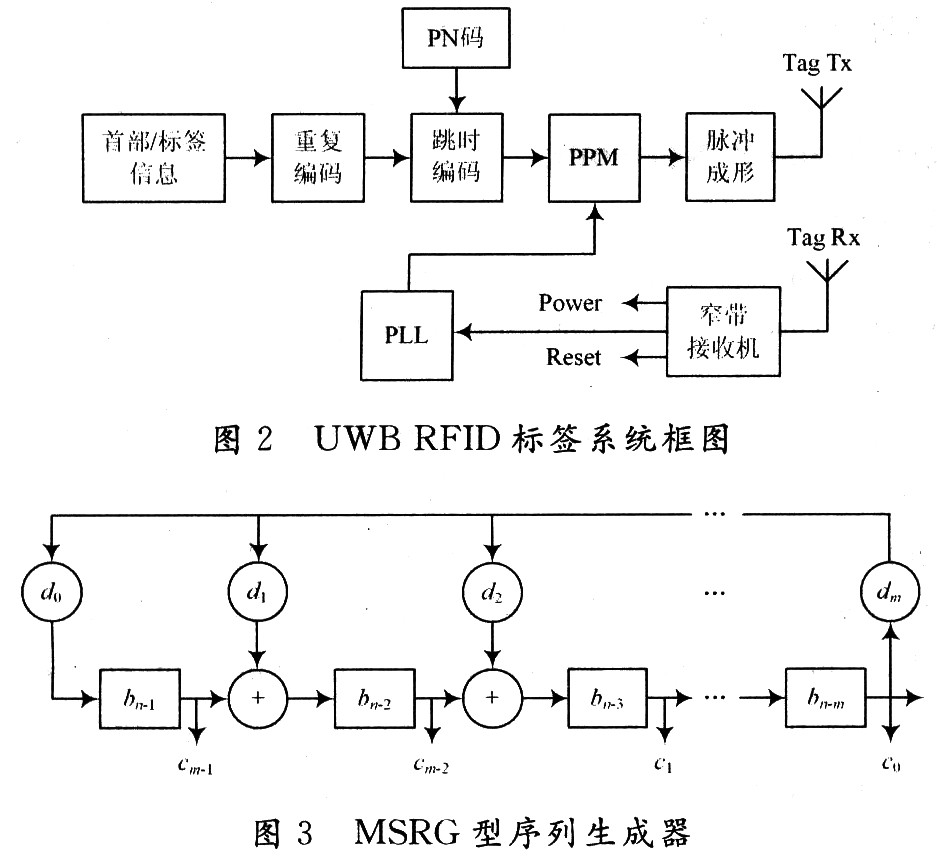
1.3 The structure of TH-PPM RFID tag display The structure of UWB RFID tag is shown in Figure 2, which is mainly composed of energy conversion supply circuit, PN code generator, PPM and pulse shaping and other modules. When the energy conversion circuit of the tag receives the signal, it converts part of the energy into the energy required by the tag, and the other part is processed by the narrowband receiver to provide the clock for the tag; if the tag has enough energy, it is based on the anti-collision algorithm Add discussion) Prepare the data to be sent. At this time, the 176 b data in the data frame of the tag is integrated to form a binary data stream, and the repeat encoder is input at a rate of Rb = 1 / Tb; Repeat the Ns encoding to increase the data stream rate to Rcd = Ns / Tb = 1 / Ts (Ts is the bit space for transmitting a symbol) to realize the channel coding of the data; then realize each pulse by time-hopping and PPM module In the positioning of the bit space and time slot, a pulse frame filter with a Gaussian multi-order differential impulse response is sent to the reader. The following mainly introduces the PN code generator and PPM modulation module in the system.
1.3.1 PN code generator The structure of the PN code generator adopts the module tap type (MSRG), as shown in Figure 3; the feedback coefficient of the MSRG type sequence generator is composed of the characteristic polynomial f (x) = c0 + c1x + The coefficient of c2x2 + ... + cixi determines that their relationship is ci = dm-i. The MSRG sequence generator is a modulo 2 adder connected between two flip-flops, so that there is no delay component on the feedback path. Compared with the generator of the feedback shift register structure (SSRG), there is no delay on the feedback branch The operating frequency of the component is fMSRC = 1 / (TI + Ta), and the mode 2 adder of the SSRG structure has an operating frequency of fSSR = 1 / (Tt + ∑Ta) on the feedback branch, so the MSRG type structure improves the generator Working rate. The m sequence generates a total of 2m-1 states, so there are 2m-1 time slots in one bit space (m is the number of stages of the feedback shift register) during time-hop coding.
1.3.2 PPM modulation module PPM modulation can be generated using a counter structure, but this structure consumes a lot of energy, and the frequency divider structure used is shown in Figure 4.
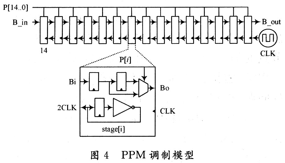
Frequency divider structure PPM modulator consists of frequency divider and trigger. Because the system chooses a 15-level pseudo-random sequence generator, there are a total of 15 modules in the figure, and each module will divide the previous module by two, and then provide the clock for the trigger of the module. Each module is driven by the clock. If P [i] is '0', the output is delayed by one clock cycle; if P [i] is '1', the output is delayed by two clock cycles. 15 modules have a minimum delay of 215-1 cycles (when P [14..0] = 00 ... 00), so the data can only be modulated on 215-1 slots after 216.1 slots, eliminating Intersymbol crosstalk between two adjacent bit spaces.
2 In the conclusion, a variety of RFID security authentication based on algorithms and protocols are compared, but this security authentication method will complicate the circuit of the label, which is not conducive to integration and cost reduction, and the label information is easy to leak, so this paper proposes a UWB-based RFID security authentication system, and did some research and simulation of some important modules. Due to the limited space and ability, there are still many problems to be discussed and studied in such a system. For example, the MAC protocol between the reader and the tag based on the UWB RFID system needs more in-depth discussion.
Electronic Cigarette Vape Pen,Electronic Cigarette And Vape Pen,Disposable Vape Electronic Cigarette Vape Pen,An E-Cigarette Vape Pen
Lensen Electronics Co., Ltd , https://www.lensenvape.com