
TL431 basic circuit and high-precision adjustable DC regulated power supply circuit TI (of course other semiconductor companies also have production, such as NXP, Motolora, etc.)) The TL431 is a three-terminal adjustable shunt reference with good thermal stability. Its output voltage can be arbitrarily set to any value from Vref (2.5V) to 36V with two resistors (Figure 2). The device's typical dynamic impedance is 0.2Ω, which can be used in many applications to replace Zener diodes, such as digital voltmeters, op amp circuits, adjustable voltage supplies, switching power supplies, and more. The specific function of the TL431 can be illustrated by the functional module shown in FIG. 1. 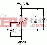 Figure 1 Schematic diagram of the internal structure of the TL431 As can be seen from the figure, the VI is an internal 2.5V reference source connected to the inverting input of the op amp. According to the characteristics of the op amp, only when the voltage at the REF terminal (in-phase terminal) is very close to VI (2.5V), a stable unsaturated current will pass through the triode, and with the small change of the voltage at the REF terminal, The current in the transistor of Figure 1 will vary from 1 to 100 mA. Of course, this figure is by no means the actual internal structure of the TL431, so it is not possible to simply replace it with this combination. However, if you design and analyze the circuit of TL431, this module diagram is very helpful to open the idea and understand the circuit. Some analysis of this paper will also be based on this module. 2. Tl431 basic application circuit
 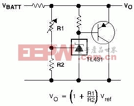 As mentioned in Figure 2, the inside of the TL431 contains a 2.5V reference voltage, so when the output feedback is introduced at the REF terminal, the device can control the output voltage by a wide range of shunts from the cathode to the anode. As shown in the circuit of Figure 2, when the resistance values ​​of R1 and R2 are determined, the two introduce feedback to the partial pressure of Vo. If VO increases, the feedback amount increases, and the shunt of TL431 increases, which in turn causes Vo to drop. . Obviously, this deep negative feedback circuit must be stable at VI equal to the reference voltage, at which time Vo = (1 + R1/R2) Vref. Selecting different values ​​of R1 and R2 results in any voltage output from 2.5V to 36V, in particular, when R1 = R2, Vo = 5V. It should be noted that the necessary condition for the TL431 to operate when selecting the resistor is that the current through the cathode is greater than 1 MA. Of course, this circuit is not very practical, but it clearly shows the way the device works in the application. A little modification of this circuit can be obtained in many practical power circuits, as shown in Figures 3 and 4.
 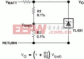 Figure 3 high current shunt regulator circuit
 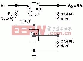 Figure 4Tl431 consists of precision 5V regulated power supply 3, TL431 high-precision adjustable DC stabilized power supply circuit resistance value: R0 take 1.5K, R1, R2 take 10K, according to the results, should get 5V output voltage. Vin uses 12V and the measured voltage is 5V. Vin uses 24V and the measured voltage is 5V (the display value of my 3 1/2 digit meter), so the accuracy of this device is very high. Connect the load, connect the load resistors at the C and A terminals, and use 12V for Vin. When the load resistance is greater than 2K, the output voltage hardly shows any change. When the resistance is less than 2K, the output voltage begins to decrease, and the condition of the cathode current mentioned above should not be met. The circuit has extremely low ripple and high precision, and can be used as a power supply for high-end appliances.
 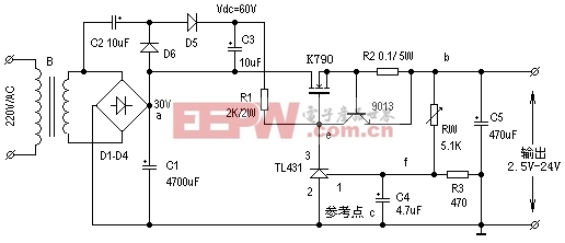 High precision regulated DC power supply made of TL431
GSM Patch Antenna,FM AM Patch Antenna,2.4G patch Antenna,4G Patch Antenna,5G Patch Antenna
Yetnorson Antenna Co., Ltd. , https://www.xhlantenna.com