
Card reader circuit schematic:
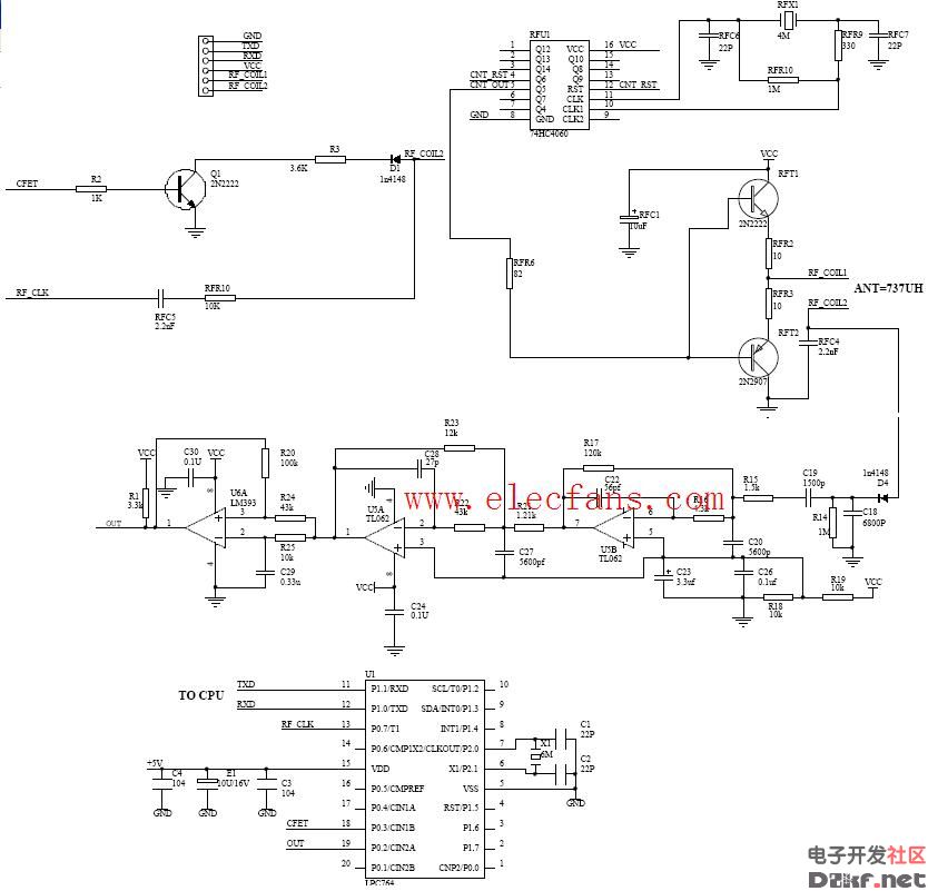
This technical documentation provides a detailed overview of the components used in a card reader system. The first image showcases an industrial router crystal, which is a critical part of the communication module. It has specifications such as size (3.2x2.5mm), model (3225), frequency (26.000MHz), capacitance (12PF), and tolerance levels (10PPM, 20PPM, 30PPM). These parameters are essential for ensuring accurate signal transmission and stability in high-performance environments. The second image features a photocoupler, also known as an optocoupler. This component is widely used to isolate electrical signals between different parts of a circuit, providing both safety and noise reduction. It’s particularly useful in applications where there is a need for galvanic isolation, such as in power supplies or data communication systems. Below the images, you can see a schematic diagram of a card reader circuit. This visual representation helps engineers understand how the various components are connected and how the system operates. The schematic includes key elements like microcontrollers, memory chips, and interface circuits that work together to read and process data from memory cards. Whether you're working on embedded systems, IoT devices, or custom electronics, understanding these components and their configurations is crucial for successful design and implementation.
9V Power Adapter,Dc 9V Power Adapter,Adapter Dc 9V,9V 8A Adapter
ShenZhen Yinghuiyuan Electronics Co.,Ltd , https://www.yhypoweradapter.com