
Abstract : Taking Microchip's PIC18F45K80 chip as the core, it has low cost. Design method of high-scalability and practical multifunctional automobile switch electrical box. In addition to the function of real-time monitoring of the starting process and driving status parameters of the car, the switch electrical box also pays more attention to the practicability and scalability of the product compared with other similar products, and has the unique function of communicating with other devices of the car.
0 Preface
With the continuous development and progress of modern automobile industry technology, the electronic equipment installed on the vehicle is increasing, so that a large number of control signals in the automobile integrated control system need to be exchanged in real time. CAN bus as a reliable automotive computer network bus has been widely promoted to various application fields of automotive control systems. The application of CAN bus technology to the car switch electrical box can enable each car computer control unit to obtain the working data in the switch electrical box through the CAN bus, and can accurately control each relay of the switch electrical box, thereby reducing the number of cars The purpose of wiring harness, improving communication reliability, reducing system cost, avoiding duplication of system functions and improving system working efficiency.
1 Design scheme of automobile switch electrical box
This switch electrical box adopts the design scheme based on the PIC18F45K80 chip produced by Microchip as the main chip. The chip not only has all the functions of a general single chip microcomputer, but also integrates a hardware CAN protocol module, which can complete CAN bus communication inside the chip. The adoption of this solution has the following advantages: First, the hardware integrates the CAN protocol module without external chips, thereby reducing product manufacturing costs; second, there is no need to write SPI interface drivers, which shortens the development cycle and improves product competitiveness; This system uses mainstream PIC chips, with strong scalability and high program portability.
PIC18F45K80 is the main control chip, responsible for the integrated transaction processing of the system.
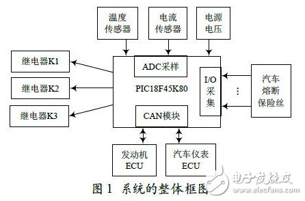
The system functions are mainly divided into four parts, namely analog signal sampling. Digital signal acquisition. The control signal output communicates with the CAN module. The collection of analog signals includes power supply voltage sampling. Temperature sensor and current sensor sampling. Digital signal acquisition on and off of each blown fuse. The output of the control signal is to the vehicle power relay K1. Start the power relay K2. Start the control of motor relay K3. CAN module communication is the one-chip computer communicates with other equipment on the car through the CAN interface chip, which is also the focus of this system. Figure 1 shows the overall block diagram of this system.
2 Hardware design of automobile switch electrical box
2.1 System main processor PIC18F45K880
The PIC18F45K80 series is Microchip's PIC18F8680. Low-cost expansion of PIC18F4680 and PIC18F4580 enhanced CAN series products. This single chip microcomputer has a wide operating voltage range of 1.8 to 5.5 V, and an on-chip 3.3 V regulator, which can be used as a power supply reference voltage. Wide operating temperature range: -40 ~ + 125 ℃, suitable for automotive working environment. The operating speed is up to 64 MHz, with a maximum of 64 KB of on-chip flash program memory, 1 024 bytes of data EEPROM, and 3. 6 KB of general purpose registers (SRAM). There are 2 internal oscillators: INTRC (31 kHz) and INTOSC (16 MHz). With extended watchdog timer (WatchdogTImer, WDT), the programmable period is 4 ms ~ 131 s.
PIC18F45K80 contains an enhanced controller area network (EnhancedController Area Network, ECAN) module. The ECAN bus module conforms to the ISO 11898-1 specification. There are 3 operating modes: traditional mode (fully compatible with existing PIC18CXX8 / FXX8 CAN modules). Enhanced mode. FIFO mode or programmable transmit / receive buffer. The message bit rate can be up to 1 Mb / s, with 6 buffers that can be used as receive and transmit message buffers, 3 transmit message buffers with priority, 2 receive message buffers and 1 A combined buffer of received messages.
2.2 CAN interface circuit module design and implementation
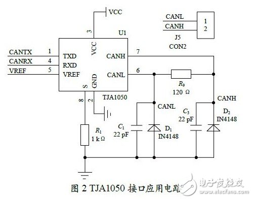
This switch electrical box uses NXP Semiconductors CAN bus transceiver chip TJA1050 as the interface between the CAN protocol controller and the physical bus.
TJA1050 can provide different transmission performances for the bus and different reception performances for the CAN controller. TJA1050 fully complies with the ISO11898 standard and has a high transmission speed (up to 1M baud). It has good electromagnetic compatibility and low electromagnetic radiation (EME) performance, and has a wide input range differential receiver, which can resist electromagnetic interference (EMI).
Figure 2 shows the interface application circuit of TJA1050. A 120-million-square-meter 9 in the circuit plays a very important role in matching the impedance of the bus. Otherwise, the anti-interference and reliability of the data communication will be greatly reduced, or even unable to communicate.
2.3 Signal acquisition and output control circuit design
The detection of various electrical working states of the automobile is one of the important working functions of the switch electrical box, mainly by the fuse state acquisition circuit. Power supply voltage and temperature acquisition circuit. Start the motor current detection circuit.
Working state detection of automobile fuses. For reliability. Accurately detect the continuity of each fuse. This system uses an optocoupler isolation method to detect the continuity of the fuse. The electrical box has a charging fuse. Heater 1 ~ 2 fuse. Switching power supply fuse. Normal fire power fuse. ON file No. 1 ~ 10 fuse. A total of 24 fuses, such as No. 1 ~ 8 fuses of normal fire. The fuse detection adopts the detection method of photocoupler isolation to avoid the interference of other electrical equipment on the car to the electrical box system.
The switch box needs to monitor the power supply voltage in real time. High voltage is achieved through voltage monitoring. Three abnormal alarms, such as low voltage and abnormal charging of the generator: Overvoltage alarm is when the voltage exceeds 32 V, the system voltage alarm is issued to the instrument through the CAN bus; low voltage alarm is when the system voltage is not started When it is lower than the set value of 23. 5 V, a low voltage alarm shall be issued, and the main power switch shall be cut off at the same time for more than 4 minutes; abnormal charging alarm of the generator means that after the vehicle is started, if the charging is normal, the current power supply voltage shall be greater than 26 V If the charging is abnormal (the power supply voltage exceeds 32 V or falls below 26 V), an alarm is issued to the instrument through the CAN bus.
Because the voltage alarm only needs to detect three voltage values, in order to reduce the system cost, this design adopts the method of resistance voltage division to detect.
This switch electrical box needs to detect the temperature in the electrical box and send the temperature data to the instrument through the CAN bus. The system uses 3899 200K NTC (Negative Temperature Coefficient Thermistor) to detect the temperature, sample the AD value after voltage division with a standard resistor, and finally check the actual measured temperature value according to the resistance-temperature table.
The other is to start the motor current detection. The vehicle starting system converts battery electrical energy into mechanical energy, and the starter drives the engine to rotate and start the engine. When the car starts, the working current of the starting motor is very large, generally up to 300 ~ 600 A. In order to prevent the overcurrent of the starter motor from damaging the car battery and other circuits, a current detection circuit is added to the starter motor. The BYD BLY2-IOV2M current sensor is selected in the system, and a metal copper sheet is used to pass through the current sensor cavity in the switch electrical box. The sensor uses the Hall effect measurement principle, a completely isolated measurement method, and has low power consumption. Features such as wide measurement range.
Guangzhou Ehang Electronic Co., Ltd. , https://www.ehangmobile.com