
0 Preface
The forward voltage drop and current of high-power LEDs are relatively large, and the power consumed is also relatively large. At present, the electro-optical conversion efficiency of high-power white LEDs is about 15%, and the remaining 85% is converted into thermal energy. The general LED chip size is only Φ2mm~Φ5mm, so its power density is very large. At the same time, unlike traditional lighting devices, the white LED's luminescence spectrum is basically in the visible range and does not contain the infrared part, so its heat cannot be released by radiation. If the heat is concentrated inside the small-sized die and cannot be effectively dissipated, This will cause the temperature of the chip to rise, causing a non-uniform distribution of thermal stress, while the chip luminous efficiency and phosphor lasing efficiency are reduced. Studies have shown that [1], when the temperature exceeds a certain level, the device's failure rate will rise exponentially. For every 2 °C rise in component temperature, the reliability of the LED will drop by about 10%.
At the same time, when the temperature is too high, the light-emitting wavelength of the white LED device will be red-shifted. According to statistics, the wavelength can be red shifted by 2~9nm at a temperature of 100 °C. As a result, the YAG phosphor absorption rate decreases, the total luminescence intensity decreases, the white chromaticity deteriorates, and the lifetime of the LED is seriously affected. At room temperature, for every 1 °C increase in temperature, the luminous intensity of the LED will be reduced by about 1%. When the device rises from ambient temperature to 120 °C, the brightness drops by as much as 35%. When multiple LEDs are densely arranged to form a white light illumination system, the heat dissipation problem is more serious. Therefore, solving the heat dissipation problem has become a prerequisite for power LED applications. Therefore, how to improve the heat dissipation capability is an urgent need to solve the industrialization of high-power LEDs. One of the key technical challenges.
1 Development of active temperature control LED
At present, almost all methods of controlling LED temperature are passive heat dissipation by increasing the heat dissipation area and improving the heat dissipation material. However, this method is limited by the ambient temperature and the power of the LED, and its effect is limited, and the controllability is poor, so the improvement is improved. The effect is often not met. Thus, a method of actively controlling the temperature of the LED using the thermoelectric cooling device TEC is proposed. This method of course also consumes energy to cool, but if necessary, it can force the LED die to cool locally, which may still have a positive effect.
1.1 How TEC works
TEC is made using the principle of thermoelectric cooling effect. The thermoelectric cooling effect refers to a function of cooling and heating when a direct current is passed through a circuit composed of a conductor having thermoelectric conversion characteristics. Semiconductor refrigeration is a kind of thermoelectric refrigeration. When a direct current is passed through a PN junction loop made of a semiconductor material, there is a thermoelectric energy conversion characteristic at the contact surface of the PN junction. This effect is also called a Peltier effect. The Peltier effect was discovered by the French physicist Pettier in 1834.
A closed loop in which two different conductors are connected. When a power source is connected to the loop, the temperature of one solder joint is lowered to the endothermic end, and the temperature of the other solder joint is raised to the heat radiating end. This phenomenon is called thermoelectric cooling and heating. Since semiconductor materials are a good thermoelectric energy conversion material, thermoelectric refrigeration devices are commonly made of semiconductor materials in the world, so they are called semiconductor refrigerators [2].
When there is an applied DC current I flowing through a closed circuit composed of two different metals, there is heat Q absorption on one joint, and heat Q is released on the other joint. This absorbed or released heat is called Hot for Pal. The relationship between the Peltier heat and the current through the conductor is:

Where π is the Peltier coefficient, which is related to the temperature difference electromotive force rate α of the material and the joint temperature T1, π=αT1. Peltier heat is only related to the nature of the two conductors and the temperature of the joint, and is independent of the rest of the conductor, and this effect is reversible.
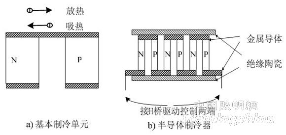
Figure 1 TEC cooling and heating principle
The basic cooling unit of a semiconductor refrigerator is a galvanic couple formed by welding a P-type semiconductor and an N-type semiconductor metal connecting piece, as shown in Fig. 1(a). When a carrier passes through a node, energy exchange with the surrounding environment is inevitable, and the change of the energy level is the essence of the phenomenon. N-type semiconductors have excess electrons and have a negative temperature difference potential. P-type semiconductor majority carriers are holes, electrons are insufficient, and have a positive temperature difference potential. When electrons pass from a P-type semiconductor to a N-type semiconductor, The energy must increase, and the added energy is equivalent to the energy consumed by the node, and the junction temperature is lowered. Conversely, when electrons flow from the N-type semiconductor to the P-type semiconductor, the temperature of the junction rises. Since the thermal effect generated by a single galvanic couple is small, the practical application of the semiconductor chiller is to use a plurality of such galvanic couples in series, as shown in Fig. 1(b), so that it can simultaneously absorb or release more. Heat. By changing the current flow across the TEC, heat absorption and release can be controlled, and the current can be controlled to control the heating or cooling power of the TEC, thereby controlling the LED temperature. Since the LED is mainly controlled to prevent its temperature from exceeding its allowable range, it is only necessary to control the magnitude of the current without having to control the direction [3].
1.2 Temperature measurement method
The temperature control device is required to control the temperature. Here, the thermistor element is used as a temperature sensor, and the magnitude of the temperature is determined by measuring the magnitude of the resistance value. In this way, it is desirable that the temperature control has a given temperature at a certain value, and the temperature actuator and the temperature detection are used as feedback to form a closed-loop automatic control system for the temperature.
The temperature signal first becomes an electrical signal that is easier to handle. Here, a temperature sensor is used to convert the temperature signal into an electrical signal. Common temperature sensors are thermocouples, thermistors, RTDs, and integrated temperature sensors. Thermistors are mainly used for point temperature measurement, small temperature difference measurement, long-distance multi-point measurement and control, temperature compensation and automatic circuit adjustment. The temperature range is -50 ° C ~ +450 ° C. Compared with other temperature sensors, the thermistor has large temperature coefficient, high sensitivity, fast response, simple measuring circuit, small size, long life and low price. Because of its large resistance value, it can ignore the error caused by the lead length. Suitable for long distance measurement and control [4].
The temperature coefficient of the thermistor is positive and negative, which can be roughly divided into NTC, PTC and CTR. NTC is a thermistor with a negative temperature coefficient, PTC is a positive temperature coefficient thermistor, and CTR is a critical temperature thermistor [37]. NTC is mainly used for temperature measurement and compensation. This topic uses an NTC type thermistor. Its main parameters include nominal resistance value Rt, rated power, temperature coefficient of resistance α, measured power, time constant, dissipation coefficient, and voltage regulation range.
In general, the temperature measurement consists of a temperature sensor and a bridge. The LED temperature measurement studied in this subject is composed of a thermistor and a differential input bridge. The temperature measurement circuit using a single bridge is shown in Figure 2.

Figure 2 Bridge temperature measurement schematic
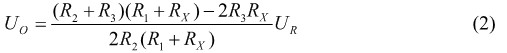
In the figure, RX is the thermistor, UR is the reference reference voltage, and the reference voltage output must be accurate and stable. Once the ripple is too large, the measurement accuracy of the bridge will be affected. The remaining resistors on the bridge arm also use precision precision resistors to ensure accurate measurement. According to the circuit and the principle of the operational amplifier, the relationship between UO and UR can be obtained [5]:
The relationship between UO and RX obtained by circuit simulation is shown in Figure 3. In the figure, UR selects 5V. After reasonable configuration of R1=1k and R2=R3, when RX changes between 0.33k~3k, the UO output is in the range of 0V~5V. In this paper, 0V~5V is used as the computer signal to represent the LED temperature signal range of -20 °C ~ 200 °C. Therefore, the temperature signal is fed back to the AD of the PIC microcontroller through the thermistor, and the temperature feedback control of the LED can be formed by controlling the current of the TEC through the single chip microcomputer.
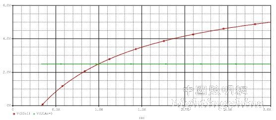
Figure 3 UO and RX relationship curve