
Many production machines want to have proper braking when parking, so that moving parts can stop quickly. Parking brakes have various methods such as mechanical braking and electric braking. Energy braking is a widely used electrical braking method.
The energy consumption braking is to cut off the running motor from the AC power supply and immediately turn on the DC power supply. When the stator winding is connected to the DC power supply, the DC current will generate a static DC magnetic field in the stator. The rotor is in the magnetic field due to inertia. The inner rotation and the induced potential in the rotor conductor cause an induced current to flow. And interacting with the constant magnetic field consumes the inertia energy of the motor rotor to generate the braking torque, causing the motor to decelerate rapidly and finally stop rotating.
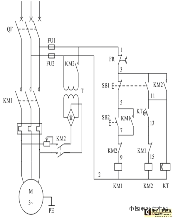
1. Close the air switch QF to connect the three power supplies.
2. Press the start button SB2, the contactor KM1 coil is energized and self-locking, and the main contact closing motor is connected to the three-phase power supply to start the operation.
3. When it is necessary to stop, press the stop button SB1, the KM1 coil is de-energized, and all the main contacts release the motor out of the power supply.
4. At this time, the contactor KM2 and the time relay KT coil are energized and self-locked, and the KT starts timing. The KM2 main contact is closed to connect the DC power to the stator winding of the motor, and the motor quickly stops under the energy consumption braking.
In addition, when the normally closed contact of the time relay KT is turned off, the contactor KM2 coil is de-energized, the KM2 normally open contact is disconnected from the DC power supply, the power supply is disconnected from the stator winding, and the energy consumption brake is terminated in time to ensure accurate stop. .
5. The overload protection of the circuit is completed by a thermal relay.
6. Interlocking link:
(1) The KM2 normally closed contact is connected in series with the KM1 coil circuit, and the KM1 normally closed contact is connected in series with the KM2 coil circuit. It is guaranteed that the KM1 and KM2 coils cannot be energized at the same time, that is, when the motor is not separated from the three-phase AC power source, the DC power source cannot be connected to the stator winding.
(2) The normally closed contact of button SB1 is connected to the KM1 coil circuit, and the normally open contact of SB1 is connected to the KM2 coil circuit. This is the interlock of the button and also ensures that KM1 and KM2 cannot be energized at the same time, and the above interlocking touch Points play the same role.
7. The DC power supply adopts a diode single-phase bridge rectifier circuit, and the resistor R is used to adjust the braking current and change the braking force.
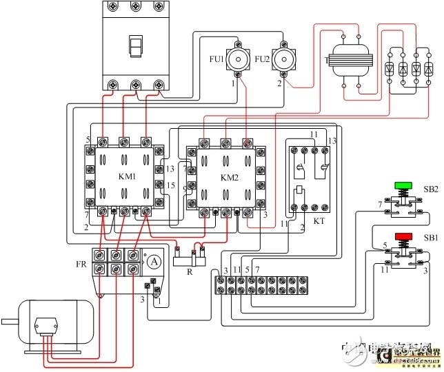
Motor full-wave energy consumption brake control wiring diagram
SMP series Bench DC Power Supplies are economical, MOSFETs-based, high switching speed, high power density desktop DC power supplies with output power covering 300W ~ 6KW, and maximum voltage up to 800VDC.
Compared with IGBT-based DC switching power supplies, MOSFET-based switching power supplies have a higher switching frequency, making this series Benchtop DC power supplies can use smaller semiconductor devices and LC filter units while ensuring low ripple, high precision, and fast response characteristics of the Benchtop Laboratory Power Supplies DC output. Which gives more space to use a smaller chassis size at the same output power, resulting the high-power density feature of this series Benchtop AC DC power supplies.


The main design purpose of this series of Bench AC-DC power supplies is to fulfill the needs of small laboratory test, precise experiment and universities.
At present, this series of Bench AC DC power supplies below 1KW adopts desktop chassis to match laboratory applications, they are mainly used in LED testing, small electroplating, heating of new materials, electrical component testing and other applications.
Bench DC Power Supplies, Desktop DC Power Supplies, Bench Laboratory Power Supplies, Benchtop AC DC Power Supplies, Bench AC-DC Supplies
Yangzhou IdealTek Electronics Co., Ltd. , https://www.idealtekpower.com