
Wired M-Bus is a bus system specially designed for data transmission of household instruments. It is a hierarchical system consisting of a master device, several slave devices, and a pair of connecting lines. The proposal of wired M-Bus meets the needs of utility meter network and remote meter reading, and at the same time can meet the needs of remote power supply. It is widely used in automatic meter reading systems in intelligent communities. However, the wired M-Bus system often needs to break walls and dig the ground during the network wiring construction process, destroying the surrounding environment. Therefore, wireless applications give it an advantage in competition, easy to install and maintain, and will not affect the surrounding environment. Wireless M-Bus is a communication standard specially used for wireless transmission of data between water meters, gas meters, heat meters, electricity meters and data concentrators. It is widely accepted in the European market.
Most meters are now powered by batteries, so the requirements for low power consumption are relatively high. In order to extend the service life of the battery, this paper selects a low-power chip Si1000 to build a wireless M-Bus communication system, and analyzes the low-power performance of Si1000 and its implementation on software and hardware.
1 Wireless M-Bus
The wireless M-Bus standard specifies the communication between the meter and the concentrator. Figure 1 shows a simple wireless M-Bus communication system, where the concentrator is the master node and the meter is the slave node.
The communication between the master node and the slave node defines three different communication modes:
â‘ S-mode static mode. S1-mode is one-way communication from the meter to other system units; S1m-mode is like S1, but the data collection device cannot enter the low-power mode; S2-mode is two-way communication between the meter and other system units.
â‘¡T-mode frequent transmission mode. T1-mode is one-way communication from the meter to other system units; T2-mode is two-way communication between the meter and other system units.
â‘¢R-mode is the frequent receiving mode. R2-mode is two-way communication between the meter and other system units.
When the meter can communicate directly with the concentrator, the other system unit is the concentrator in Figure 1. However, in practical applications, the slave node instruments sometimes cannot directly communicate with the master node concentrator, so routing nodes are needed to transfer the data between them. At this time, the system unit is a high-performance gateway.

2 wireless M-Bus transceiver system design
2.1 Principle of wireless M-Bus transceiver system
The functional block diagram of the meter reading wireless transceiver system is shown in Figure 2. Wireless data transmission and reception is realized by the wireless microcontroller Si1000. The sending module inside the master node Si1000 encodes the data and sends it to the receiving module via the antenna in a specific format. After receiving valid data from the receiving module inside the node Si1000, the microprocessor inside the Si1000 reads the data of the external instrument through the expansion interface, adjusts and converts it accordingly, and sends it to the master node through radio frequency. The master node communicates with the central copy center through GPRS.
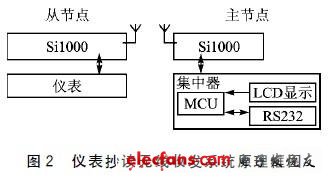
Because it uses a wireless microcontroller, the master / slave node send / receive module does not need to use the traditional MCU + RF module design method, and only needs a piece of Si1000 to complete radio frequency communication.
2.2 RF section
As one of the members of Si10xx series, Si1000 combines 8051 core, high penetration penetrating EZRadioPRO RF transceiver with operating frequency of 240 ~ 960 MHz, 64 KB Flash and 10-bit ADC in a very compact 5 mm & TImes; .Si1000 series provides superior RF performance, with the characteristics of the highest output power, receiving sensitivity and the lowest power consumption wake-up conversion. The wireless microcontroller has the lowest current consumption (160μ / MHz) in the operating mode. In the sleep mode, the current consumption is as low as 315nA when the RTC uses the internal low frequency oscillator (LFO) as the frequency source. In mode, only 25 nA operating current is required, and RAM data is not lost. Figure 3 shows the RF hardware schematic.
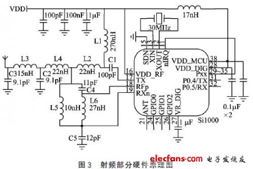
From the node, the meter is connected to the UART serial pins P0.4 / TX and P0.5 / RX of the Si1000 chip. The UART serial port pins P0.4 / TX and P0.5 / RX of the master node chip Si1000 are connected to the concentrator. The MCU serial port inside the concentrator is connected to the GPRS module through RS232, and the remote transmission of data is realized by means of mobile network and Internet. The programmable load capacitors in the figure can be integrated, and the values ​​of L1 to L6 and C1 to C5 are determined by the frequency bandwidth, antenna impedance, and supply voltage.
The communication of the wireless transceiver module is sent in the form of data packets. The wireless sending program is responsible for writing data. Refer to the wireless M-Bus communication protocol to add the preamble, synchronization word, data payload length and CRC check byte to the data. Form a data packet and send it out. To ensure the correctness of the received data, the wireless receiving program is responsible for receiving data packets and checking the CRC bytes.
RAM/RFM Intermediate Frequency Capacitors
RAM/RFM Intermediate Frequency Capacitors
Intermediate Frequency Capacitors,Induction Heating Capacitors,Furnace Resonant Capacitor
YANGZHOU POSITIONING TECH CO., LTD , https://www.yzpstcc.com