
There are two main methods for CAN communication design: one is voting method or trial and error method based on engineering experience, and the other is design method based on system engineering technology. The trial and error method is to design the CAN communication protocol by integrating the experience accumulated by the component suppliers in different projects. The system engineering method is based on a certain theoretical idea, considering the system-level requirements of communication to design the communication protocol.
In the trial and error method, since each component supplier considers the need for the protocol based on the needs of its own parts, it is impossible to consider the interaction and function between the components from the perspective of the entire system. Therefore, there are potential design errors in the results of integration of different requirements, and these errors are difficult to find in the simulation process, and cannot be solved by means of testing.
The system engineering rule starts from the system-level requirements, fully considers the interaction and requirements between components, and designs communication protocols at the system level. Therefore, the design results can be optimized during the design process, and the correctness of the design results can be verified. The following sections provide a detailed introduction to the system engineering design method.
Main content in CAN protocol designThe main content of the CAN protocol design is to create messages, assign message priorities and determine the period of the message. The basic principles of CAN communication are analyzed below to illustrate their importance.
The CAN bus uses a multi-master structure, CSMA/CA (Carrier Sense MulTIple Access/Collision Avoidance) and a bitwise arbitration mechanism to determine the nodes that access the bus. CSMA/CA means that the node is also listening to the bus while transmitting, and collision avoidance has been avoided. The bitwise arbitration specifies that the dominant signal is preferred over the recessive signal. When the dominant signal and the recessive signal are simultaneously sent to the bus, the bus The above is a dominant signal. In the present text, the dominant signal is represented by "0", and the recessive signal is represented by "1". In the example below, we also use low level for dominant signals and high levels for recessive signals.
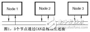
To illustrate the main problems in the design, the following is an example of bus communication with three nodes. As shown in Figure 1, three nodes are connected to each other through a CAN bus.
The internal program of each node determines when data needs to be sent over the bus, and the message has a fixed format. As shown in FIG. 2, the CAN message is composed of fields such as a start bit SOF, an ID field, and a control field. The ID field represents the priority of the message. When there is bus competition, according to the principle of bitwise arbitration, the ID has a small priority and the message is sent preferentially. Figure 3 is an example of arbitration. It is assumed that at a certain moment, three nodes send messages at the same time. The message ID (binary format) sent by each node is: ID1=11001101010, ID2=11001011011, ID3=11001011001. Each node begins by sending a SOF bit and then sends the ID field bit by bit. A node that does not send a message automatically switches to a receiving node after listening to the SOF bit. The arbitration between the sending nodes occurs in the process of ID transmission. During the sending process, the sending node is simultaneously listening to the signal on the bus. As long as the sending signal is consistent with the monitored signal, the sending process will continue, otherwise it stops. As shown, node 1 transmits a recessive signal on bit 6, but the signal on the bus is a dominant signal. Node 1 stops transmitting and becomes a receiving node. At the 10th bit, node 2 sends a recessive signal, but the bus is a dominant signal, so node 2 stops transmitting and turns to the receiving node. At this point, the arbitration ends and node 3 arbitrates and continues to send the remaining data bits.
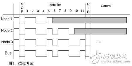
As can be seen from this process, since the message ID3 has a high priority, it is sent preferentially. Both ID1 and ID2 need to wait for the next arbitration decision to send. That is to say, the result of each arbitration is that the transmission of some messages is delayed.
In addition, the CAN protocol stipulates that the message will not be released if the message is not sent. Therefore, when a message with a low priority is sent, a message with a high priority is also delayed.
Delay is also a major problem affecting the performance of CAN communication. If the message delay time is too long, it will affect the function of the receiving node, and serious accidents may also occur. Therefore, one of the important contents of the CAN protocol design is that the delay time of the control message is at a reasonable level.
The message priority and period are the main factors affecting the delay in the design. Reasonable allocation of ID and determination of the period of the message can effectively control the delay. Therefore, one of the main contents of the CAN protocol design is how to properly allocate the message ID and determine the period of the message. Creating a message is also one of the important things, but the impact on latency is relatively small.
The system engineering design method of the CAN protocol further quantizes the interaction between functions by analyzing the time in communication, thereby further creating a message, assigning a message ID, and determining its period.
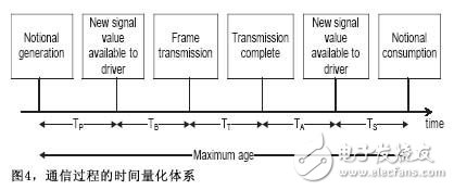
CAN protocol system engineering design method The essential difference between the system engineering design method and the trial and error method is that the quantitative system is used to obtain the time requirement in the communication process. Figure 4 shows the time requirements for communication. TP is the time interval between the time the event occurs and the data is ready to be sent to the driver. TB is the time interval between when the data is grouped and ready to be sent to the bus. TT is the actual transmission time. TA is the message received. The time interval between when data can be used by the application, and TS is the time interval between when data can be used to actual use. The entire communication process must be completed within the specified time, and this time is the maximum age. This time marks the real-time nature of the data transmission. As long as the data is sent to the receiving node within this time range, the function of the receiving node will be executed in real time.
In addition to these parameters, the complete system design requires the following information:
â— Signal definition: type, size, etc.
â— Send node data definition: the definition of the transmitted and received signals, TP and TS;
â— Receive node data definition: definition of the received and received signals, TP, TS, and maximum age;
â— Definition of topology: the interconnection between nodes.
Based on the above data, the real-time nature of the communication process is analyzed to calculate the delay in communication. The message ID is then assigned and the period is set according to the deadline monotonic analysis.
Based on the time requirements acquired by the system, the system calculates the delay of the message and verifies that the designed protocol meets these time requirements. If the time requirement is not met, the system will automatically adjust the message ID and period until all time requirements are met.
This article was experimented with the design tool VNA of the Mentor Graphics Volcano product line. VNA is the automation design tool of CAN/LIN protocol. The core idea is to adopt the system engineering design method introduced in this paper. The usage method can be as shown in Figure 5. The user provides the signal and node definition, the time parameter definition introduced in this paper and the project management definition. The VNA will automatically design the CAN communication protocol and output the communication protocol specification.
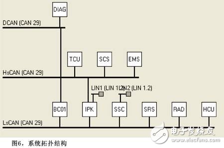
Figure 6 is the communication system topology of this experiment. The system consists of three CAN buses and two LIN buses. The CAN protocol uses 29 bits.
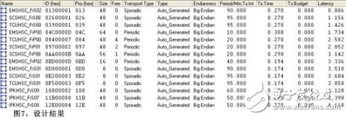
After inputting the parameters, the VNA automatically generates a communication protocol, and the result is shown in Figure 7. The ID of the message EMSHSC_FrP00 is 0x04c000d, the period is 10ms, and the calculated delay time is 1.734ms.
The system engineering design method uses a set of quantitative systems to describe the complete process of data transmission and reception. These indicators are clearly defined and the timeliness of the system's functionality is clearly described. Because of this, automated design agreements are made possible.
According to these quantitative indicators, the system will automatically calculate the delay time of the message, and automatically adjust the priority and period of the message to control the delay time of the message, to ensure that the time requirements of the user are all satisfied, thereby realizing the control of the message delay from the design perspective. purpose.
The automation design agreement reduces the technical threshold of protocol design, especially for Chinese OEMs, and there is no experience. Such tools will help the development of domestic independent products on the bus.
Lcd Display Panel,Flat Panel Monitor,Lcd Touch Screen,Lcd Tv Panel
Huangshan Kaichi Technology Co.,Ltd , https://www.kaichitech.com