
1, infrared emission protocol
The infrared emission protocol has been written in previous articles and will not be repeated here.
2, timer count and input capture
The timer is to increment or decrement the count value according to a specific frequency, and generate a flag or interrupt when the value overflows.
The input capture of the timer is to measure the pulse width of the input signal.
This is achieved through the combination of normal counting and input capture.
3, to achieve the method
The time of the high pulse of the input signal is recorded by the timer, and it is judged by this time whether the data is the sync header information, the data 1 or the data 0.
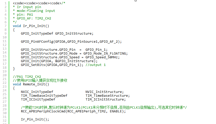
Second, to achieve1, configure the timer 2 input capture channel
The PA1 pin is used in the sample code and is configured as a pull-up input mode. The alternate function is channel 2 of timer 2.
The timer uses a normal timer, Timer 2, which has an input capture function.
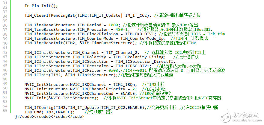
Two operating modes of the timer are configured, one is an ordinary counter TIM_TImeBaseInit, and the other is an input capture mode TIM_ICInit.
Configure the interrupt source of Timer 2, there are two interrupt sources, one is the TIM_IT_Update interrupt, and the other is the input capture interrupt TIM_IT_CC2.
The configuration code is as follows:
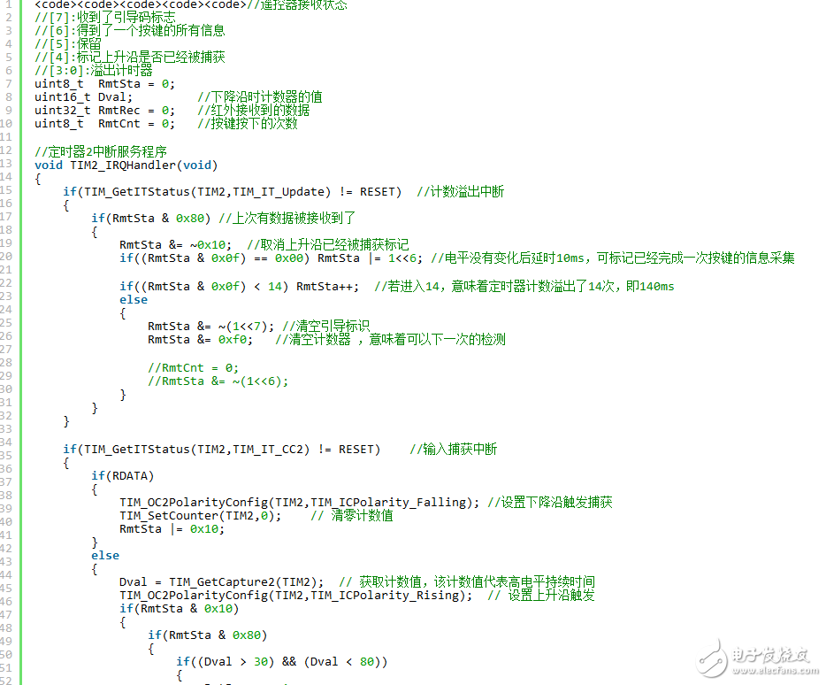
2, add timer 2 interrupt service function
Two types of timer interrupt sources are used, count overflow interrupts and input capture interrupts. However, the interrupt service function that triggers the interrupts in both ways is the same one, void TIM2_IRQHandler(void).
The timer uses the TIM2 general-purpose timer and the mode is counting up. In this mode, the counter counts from 0 to the autoload value (the content of the TIMx_ARR counter), and then starts counting from 0 again and generates a counter overflow event. The period of the timer count overflow is 10ms. The generation of this interrupt shows that there is no input capture to clear the count value within 10ms, that is, the input signal does not change, indicating that 10ms has not received the infrared signal, so it can be judged that the reception is completed.
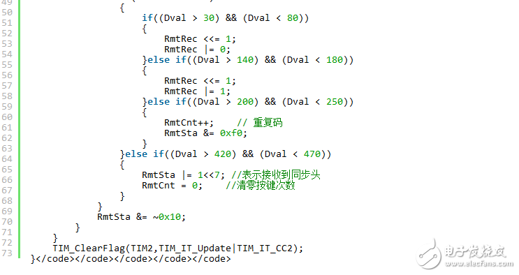
The input capture is to measure the duration of the high level, so use the rising edge to trigger the interrupt, clear the count value, switch the next time to the falling edge trigger; when the falling edge triggers the interrupt, write down the count value and switch the next time to rise. Along the trigger. Therefore, the time recorded on the falling edge is the high-level timing time. The reason for recording the duration of the high level is that the infrared signal is the same as the duration of the low level when it represents logic 0, logic 1, and the duration of the high level is different.
The sample code is as follows:
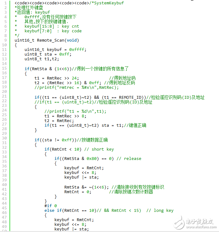
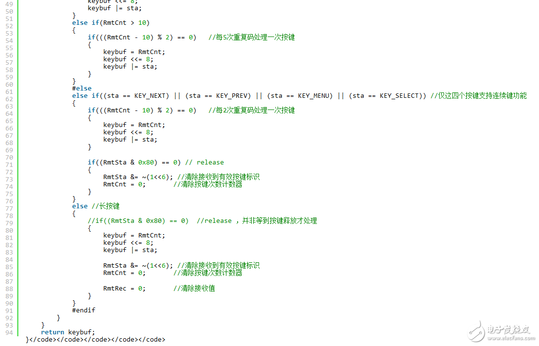
3, infrared button scan function
This function is placed in the main loop and the rotation training determines whether the key reception is completed. If the reception is completed, analyze the key value.
This function returns a 16-bit value, where the lower eight bits represent the key value, and the upper eight bits represent the number of presses, in turn analyzing long and short keys. This is mainly achieved through the provisions of the repetition code in the infrared protocol.
According to the infrared protocol, if you press a key and do not release it, the repeat code will be sent with a period of 108ms. The repetition code shows a high level of 2.25ms.
The sample code is as follows:
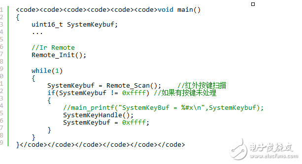
4, the main function
In the main function, initialize the IO port and timer.
In the main loop, the received key control code is printed by judging the reception completion flag.
The SystemKeyHandle() function handles the logic of each keystroke.
The sample code is as follows:
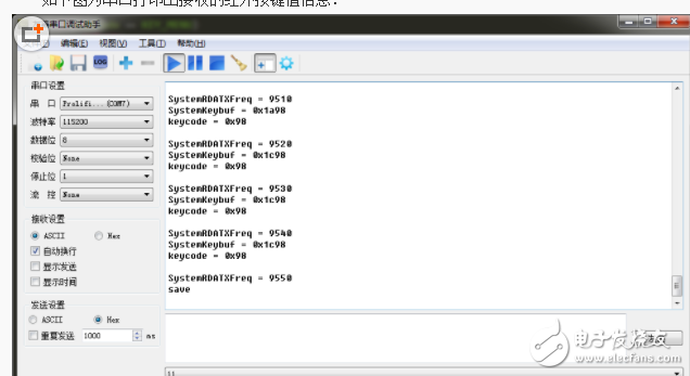
The following figure shows the serial port print out the received infrared key value information:
Dunke Disposable Vape Pod Vape


Disposable vape pod hqd eifbar bang usvape ukvape hyde cali
Nanning Nuoxin Technology Co., LTD , https://www.nx-vapes.com