
Pick   To: Adopt wireless transmitting and receiving module, combined with single chip microcomputer control, design a wireless data transmission system of pressure sensor. The actual debugging shows that the performance meets the design requirements and the transmission distance reaches dozens of meters.
introduction
In today's informatization era, sensors, functional devices for sensing, collecting, converting, transmitting, and processing various information have become indispensable and important technical tools in various application fields, especially in automatic monitoring and automatic control systems. In some fields, due to the limitation of conditions, the use of ordinary wired cables to extract signals cannot meet the requirements or can not be realized. In recent years, wireless communication technology has made great progress, especially the progress of digital circuits and radio frequency circuit technology, making wireless communication more economical and reliable. This paper uses a dedicated wireless transceiver module to design a wireless data acquisition scheme based on a pressure sensor.
Overall system design
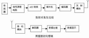
The system consists of two parts: data acquisition and transmission, and data reception and processing. The data acquisition and transmission part mainly takes the single-chip microcomputer as the core, and also includes sensors, signal conditioning circuits, digital-to-analog conversion circuits, and data transmission modules. Data reception processing is to digitally display the received data. The overall system block diagram is shown in Figure 1 .
data collection
The system acquisition mainly uses Atmel 's AT89C51 microcontroller as the control processing core, which completes the data collection processing and wireless transmission of control data. AT89C51 microcontroller is a low-power / low-voltage / high-performance 8 -bit microcontroller with a 4KB programmable / erasable / read-only memory on -chip ; its output pins and command system are compatible with MCS-51 . The signal organization circuit mainly uses the instrumentation amplifier AD623 to amplify the weak differential signal collected by the sensor. AD623 is a low-cost, high-performance instrumentation amplifier of American Analog Devices . The digital-to-analog conversion circuit uses ICL7135 to convert the collected analog data into digital data. It is a four and a half double integral A / D converter, which has the advantages of high precision, low price and strong anti-interference ability.
The data is sent to the single-chip microcomputer after conditioning and digital-to-analog conversion. The single-chip microcomputer processes the received data, and then sends the pressure data to the digital display circuit through the wireless transmission module and the receiving module to display the data.
Picture 1 Â System Block Diagram
Â
Picture 2 Transmitting circuit
Â
Picture 3 Â Receive circuit
Wireless data transceiver system
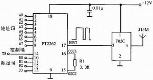
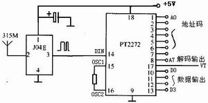
The transceiver system consists of two parts: the transmitting unit ( Figure 2) and the receiving unit ( Figure 3) . The working principle is: the microcontroller outputs 4-bit parallel data to the encoder PT2262, PT2262 4-bit parallel data is encoded into a serial signal into the transmitter module F05C, through the antenna out; signal receiving module receives sucked Perform demodulation, and then send it to the decoder PT2272 to decode, and decode 4 bits of parallel data.
This system uses a dedicated transmitter module F05C and a receiver module J04E . The pair of modules is a low-speed data transmission module designed for wireless transmission of this encoding circuit. The module is encapsulated in SMT resin, small in size, working at 315MHz frequency, and can be sent and received continuously for a long time. Transmitting module F05C adopts the sound meter resonator to stabilize the frequency, the frequency consistency is good, and it is free of debugging. It is especially suitable for the wireless remote control and data transmission system with more sending and receiving. It has a wide operating voltage range and low power consumption characteristics, 12V is the best operating voltage, and the emission current is about 5-8mA . In addition, F05C contains an isolated modulation circuit to eliminate the influence of the input signal on the RF circuit . The signal is directly coupled , and the stable performance of the encoded signal can be directly connected to the F05C data input terminal. The receiving module J04E adopts a unique super regeneration circuit structure, which contains amplification and shaping, and the output data signal can be directly sent to the decoder. It is extremely convenient to use and is a super cost regeneration module with good cost performance. , J04E has very low power consumption, only consumes 0.2mA current at 3V , can be in a standby state for a long time.
The codec PT2262 / 2272 is a low-power low-cost universal codec circuit manufactured by CMOS process. The sending end PT2262 outputs a 12 -bit code, the upper 8 bits are the address, and the lower 4 bits are the data. When sending, the 12 -bit codes are sent in order of high-order first and low-order second. The logic state of the address code is " 0 ", " 1 ", "floating", and the logic state of the data code is " 0 ", " 1 ". When the address received by the receiving end PT2272 is the same as the address set by itself, the received data is decoded and output.
The A0 ~ A7 pins of the PT2262 encoder are address pins, and each bit has three logic states: " 1 ", " 0 ", "floating" , Any combination can provide 6561 address codes; D0 ~ D3 pins are data pins, each bit has " 0 ", " 1 " two states ; OSC1, OSC2 are oscillator pins, external oscillation resistance can be generated Oscillation; TE pin is the sending enable terminal. Give it a low level to trigger the oscillator to generate oscillation. The address and the input data are encoded together. The modulated serial digital signal is output via the DOUT pin. 8 bits The address code and the 4 -bit data code form a code word, A0 is the first bit . PT2272 is a decoder paired with PT2262 , where the address codes A0 ~ A7 must be set the same as PT2262 in order to latch and output the received data; DIN is the data input pin, VT is the effective output decoding effective confirmation output ( often Low ) , the decoding effectively becomes high level. PT2262 each transmission data when transmitting at least 4 codeword sets, PT2272 decoder chip after receiving the signal, the address code, after checking the two comparison, VT pin outputs a high level only while the received lock D0 ~ D3 Save and output.
Display circuit
In order to simplify the circuit and reduce the cost, this system uses dynamic scanning drive. The drive of the nixie tube includes bit-selection drive and segment-selection drive. The segment-selection drive uses segment-selection control to display different characters, and the bit-selection drive uses the bit-selection control to control the brightness of a certain bit of the display. This system uses the lower 4 bits of the P1 port to drive the 4 -bit BCD latch / decoder / driver MC14543 . The output of the MC14543 is connected to the seven-segment input of the LED to directly drive the digital tube. The position selection drive is driven by the inverter 74LS04 , so when the software bit scanning is implemented by the single-chip programming, the position selection of the common negative digital tube should be reversed. The display process is as follows: (1) Send the data into MC14543 , and drive the digital tube through decoding; (2) Send the bit selection signal to 74LS04 , drive a certain bit of the display to turn on after the reverse direction, and delay. (3) Modify the data pointer to the next character to be displayed and repeat the above process.
Conclusion
This paper introduces a wireless data acquisition and transmission scheme based on a pressure sensor. The test shows that the transmission distance reaches tens of meters, which is suitable for inconvenient connection testing and remote display occasions.
AA battery is 1.5V lithium battery with high capcacity, the cycle life is more than 1000 times, 1-2 hours can be fully charged. USB charging, one set with the battery box can be a charger.
Self-discharge small, good battery, under 2% per month (recoverable). No memory effect. The operating temperature range is -20℃ ~ 60℃. Excellent cycle performance, fast charging and discharging, charging efficiency up to 100%, and large output power. Long service life. It does not contain poisonous and harmful substances and is called green battery.Environmentally Friendly AA Battery,AA Battery USB Charger,AA Battery Rechargeable 1.5V,Rechargeable AA Batteries With Charger,1850mWh AA Battery Replacement,AA Battery With Micro USB Charger
Shenzhen Enershare Technology Co.,Ltd , https://www.enersharepower.com