
EL34 (6CA7) is the first audio power pentode tube introduced by Philips in 1956. At that time, its appearance brought an improvement to the audio quality of audio amplifiers. table). Today, the tube produced by China Shuguang Electron Tube Factory is sold well both at home and abroad. The beauty of the sound reproduced by EL34 is beyond the reach of transistor amplifiers. In today's world where transistor amplifiers dominate, it is not old, and the hero is still there for this reason.
First, the characteristics of the tube
The electronic tube is the first electronic amplifier device in human history. Speaking of the working principle of the electron tube, it is an old and new topic for current fans. Due to certain prejudices and energy relations, our country stopped the introduction and application of electron tubes across the board after the 1970s, which undoubtedly caused difficulties for the current bile duct fever. Here, it is necessary to express some common sense of the electron tube.
Electron tube is a kind of vacuum device that uses the principle of electric field. When analyzing its work, I can understand it according to the common N-channel junction field effect tube workpiece method. It is easy to get started. It is just that the electron emission of the cathode of the electron tube needs to be heated. The gate control characteristics and working principle of the two are very similar.
Compared with the current transistor amplifier, the tube amplifier has its own characteristics: first, the temperature of the tube itself is stable, and there is no need for a huge heat sink that is indispensable in the transistor machine; second, the load capacity is strong, and it is not as delicate as the transistor. It really takes more than tens of minutes to burn a tube, so the device is relatively safe during the experiment. The third is that the tube amplifier is determined by the characteristics of the device, and the load speaker needs to be connected through the transformer. In the event of a machine failure, the expensive speaker system will not be compromised like a transistor machine.
Pay attention to when making and using the vacuum tube machine: high voltage inside the machine, be careful of electric shock! The reliability of the component withstand voltage is high, and live welding is strictly prohibited. In addition, the electronic tube is strictly forbidden to be empty, and the speaker must be connected during the test machine.
The electron tube is a kind of vacuum electronic amplifier device with high internal resistance and high voltage operation. Its biggest advantage is that it has approximately ideal linearity of amplification. This advantage cannot be achieved by the existing transistors, which makes its application circuit very simple. It does not need to use a lot of active devices for "common base-common radiation" connection like transistor amplifiers. This corresponds precisely to the creed of "simpleness first" in the fever world. This is one of the most important reasons why it can lead the ring in today's highly developed electronic technology.
Second, the tube output transformer
The output impedance of the electronic tube is higher, and its equivalent resistance is several orders of magnitude higher than the impedance of the currently widely used electric speakers. From the perspective of impedance matching, it is necessary to use the output transformer for impedance transformation: Moreover, the electronic tube The power of the amplifier is in the form of high voltage and small current. From the perspective of low-voltage high-current energy required to drive low-impedance speakers, it is also necessary to use a step-down transformer.
For the rapid development of modern audio sources, according to the requirements for reproducing high-fidelity program sources represented by CD players, the indicators of amplifiers are very important. For tube amplifiers, this index depends largely on the quality of the output transformer. The quality of the output transformer is very important. Because this article is to introduce a British finished machine kit, no specific production is introduced, and now only the transformer design and process should pay attention to the issues to be discussed.
1. The turns ratio of primary to secondary is obtained based on the output impedance of a particular tube and the impedance of the speaker being driven. Therefore, to maximize the performance of the tube, it is important to choose a specially designed output transformer.
2. In order to obtain a very low frequency response of the transformer, the inductance of the primary coil must be made larger: starting from the high frequency characteristics and phase characteristics, the parasitic capacitance and leakage inductance of the transformer itself should be made as small as possible . Traditional transformers premised on radios and general-purpose amplifiers are obviously not up to the modern requirements.
3. Transformer with electronic tube as push-pull output. According to the output stage, the power electronic tube works in parallel at both ends of the power supply in the DC state, and the signal working state is positive and negative. In the direction of the wire, the DC current flowing from the "center tap" through the two half-windings will produce magnetic field lines in the opposite direction, canceling each other inside the iron core, so that the static magnetic field of the iron core in the transformer is zero It is very important to fix the magnetic flux of the iron core to prevent saturation distortion of the iron core and reduce the transformer volume. At the same time, the ripple components on the power supply due to poor filtering can also be mutually suppressed within the transformer, which is conducive to improving the signal-to-noise ratio.
The process of the tube output transformer is very strict, and it is very difficult to solve the above contradictions. This is one of the main reasons why high-quality output transformers and tube amplifiers are now expensive.
Third, the principle of the tube push-pull output stage
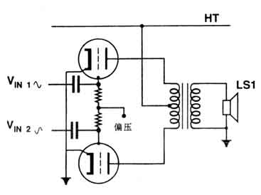
Figure 1 Simple output stage
Fig. 1 shows the circuit structure diagram of a common tube push-pull output stage. The two anodes of the amplifying electron tube are respectively connected to both ends of the output transformer. The working power supply HT flows through the primary tap of the output transformer through the primary winding to supply power to the electron tube. The load (speaker) is connected to the secondary side. The circuit uses a "fixed bias" type circuit: the cathode of the tube is directly connected to the ground (common point), the grid is connected to two resistors, and the common point is connected to the negative bias power supply that meets the normal operation of the two tubes. This is The typical configuration method of the normal operation of the electron tube. There is also a "self-bias" method for setting the DC working point of the electron tube, which is to insert a resistor in the cathode circuit of the electron tube, and use the DC current flowing through the electron tube circuit to generate a certain voltage drop on the resistance to make the cathode There is a positive potential difference with respect to the "ground" potential. At this time, the gate of the electron tube can be connected to the ground potential, which can reduce the trouble of adding circuits and components due to the configuration of the gate bias power supply. This kind of so-called "self-biased" type circuit is also widely used, but the cathode resistance will consume part of the voltage and the output power will be reduced.
The working bias of the tube is different for each model. In addition, the same type of tube requires different grid working bias voltage when different anode working voltages are obtained. Generally, the higher the voltage, the grid bias voltage should be more negative. On the contrary, if the parameters are not used during the application Given the anode high voltage, the absolute value of the grid bias voltage will be reduced. The typical working parameters of the electronic tube can be found in the relevant manual. Moreover, the production dispersion of the electron tube is much smaller than that of the transistor. It can be said that the setting according to the manual is generally no problem.
The signal amplification path of the push-pull tube amplifier circuit is divided by the previous stage, and two symmetrical signal voltages that are opposite to each other are obtained to enter the grids of the two tubes, and the electron flow emitted by the cathode is modulated to be amplified in Yangying. The resulting signal voltage is combined into the transformer and output to the load speaker through the transformer coupling. The internal connection of the output transformer, the end with the same name is shown in the figure above, so that the DC ripple (AC component) contained in the two anode power supplies can be reversed inside the transformer, and the inverted signal component is converted to the same phase inside the transformer Enhanced. The power is generally increased to about twice that of a single tube. (The output efficiency of specific Class A, Class A, Class 1, Class 2, Class 2 and Class B working conditions is not compared here, this machine is Class A and Class 1 working state. For triode, beam quadrupole, pentode and popular ultra-linear The status is not discussed here because of the many aspects involved, the machine is a typical pentode working mode).
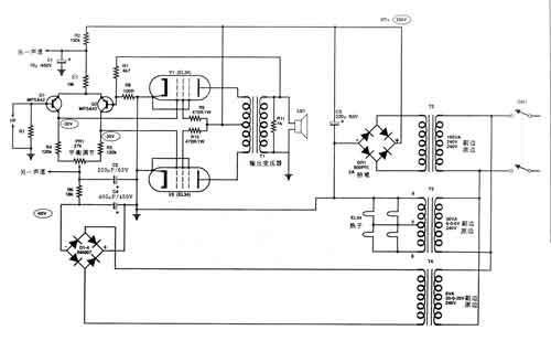
Figure 2 the full circuit of the mixed power amplifier (one channel)
Figure 2 shows the circuit diagram of the hybrid power amplifier. After discussing and explaining the special points of the tube amplifier above, let's analyze the whole machine. I believe everyone understands it better.
The figure shows the circuit of one channel of this stereo amplifier, and the circuit of the other channel is exactly the same. The analysis of this amplifier from the schematic diagram can be divided into three parts:
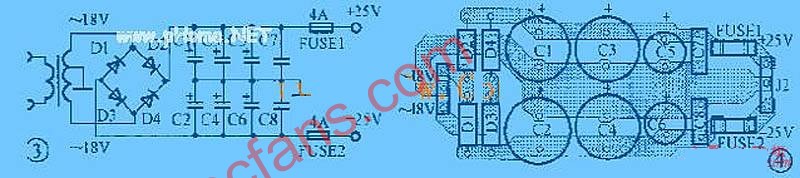
1. Power supply, which includes the high-voltage HT supplied by the vacuum tube amplified anode power supply, the 6.3V voltage heating the EL34 "heater" (commonly known as the filament) of the heat-heating tube, and the -60V DC voltage and high voltage HT obtained by the rectification of the transformer T / t The power supply for transistor Q1 and Q2 work together.
2. Push-pull power amplifier stage composed of electronic tubes V1, V2, surrounding components and output transformer.
3. The differential voltage amplifier stage composed of transistors Q1 and Q2. This level has three main functions:
a. Form a differential voltage amplifier to amplify the weak signal voltage input from the output to a voltage sufficient to drive the power amplifier EL34: b. A simple differential amplifier completes the phase separation of the signal voltage to produce the balanced voltage output required to drive the push-pull amplifier. c. The whole circuit starts from improving performance. Using DC coupling without capacitive coupling, the static DC bias of the tubes V1 and V2 (the unit is 30V) is also obtained by the collector potential of the transistors Q1 and Q2. It is not as common as the RC coupling mode. Set the static adjustment element of the tube.
This design of this machine has a great advantage that the general design cannot achieve. That is, the two stages of the amplification part are symmetrically balanced design, which has a high common mode rejection ratio. Therefore, The ripple and power interference signals brought by the power supply can be automatically cancelled and suppressed inside the amplifier. Therefore, the amplifiers designed and installed in this design have very low noise indicators such as hum and noise, and the signal-to-noise ratio is fully qualified for the requirements of digital audio amplifiers.
The input signal is directly coupled from the base of the transistor Q1 into the power amplifier input stage. Q1 and Q2 form the differential voltage amplifier stage, R3 is the common emitter resistance of this differential amplifier, the resistance of this resistor is very large, and has a relatively constant current characteristic, which improves the common mode of the differential amplifier and the It is very necessary to obtain the appropriate Q1, Q2 working current and emitter potential. Its resistance value plays an important role in the setting of working current. Resistors R4, R5, and PR1 are the collector load resistance of this differential amplifier. In order to increase the voltage gain of the input stage, this resistance value is relatively large. PR1 is set to overcome the problems of large discrete transistor parameters and poor matching performance. It has the dual functions of fine-tuning the two valves to control the DC static operating point of the grid and adjusting the AC noise self-suppression. The total resistance of resistors R4, R5 and PR1 and the voltage drop generated by the operating current of the differential amplifier will determine the bias voltage of the control gate of the power amplifier tube. The collectors of the two transistors are directly output to the control gates of V1 and V2, which pushes the power amplifier tube to perform power amplification.
At the positive and negative power supply terminals of this level of power supply, a decoupling filter circuit composed of R2C1 and R6C2 is established.
The power amplifier is very simple. The principle of the power amplifier stage has already been discussed above, and will not be repeated here. This machine adopts push-pull fixed bias pentode power amplifier circuit. Resistor R9R10 is the power supply resistance of electron tube curtain grid. Its value is set according to the given EL34 model. Transformer T3 is the power supply of the electron tube EL34 thermon. One end of the secondary connection thermon is connected to the common potential, which is very useful for reducing the hum produced by the tube.
The machine has set a certain negative feedback loop. The hot end of negative feedback is obtained from the secondary of the output transformer through resistors R7 and R8, and a part of the output signal is sent to the inverting input terminal (base of Q2) of the input stage differential amplifier. The repulsion ratio of the transformer jointly determines the amount of negative feedback, and can control the input sensitivity of the whole machine. The input sensitivity of this machine is 650mV at rated output power. The negative feedback loop has a great effect on reducing the equivalent internal resistance of the beam-emitting quadrupole tube and pentode and reducing the distortion coefficient of the whole machine. The tube amplifier will not have the so-called transient intermodulation distortion of the transistor machine, and it is beneficial to obtain certain negative feedback.
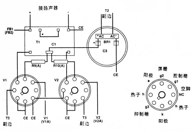
Figure 3 Output stage wiring
Five, the choice of electronic tube machine components
Attached is a list of components required by the machine. Please configure according to the given parameters. The power supply voltage inside the tube is very high. Special attention should be paid to the reliability of the devices that withstand high voltage. Is the insulation withstand voltage parameter sufficient? To avoid unnecessary troubles caused by poor component quality when installing and adjusting the machine!
Six, the installation of the whole machine
The tube amplifier needs to have a large mechanical strength chassis base. This machine is made of aluminum alloy plate with a thickness of 2 mm to make the bottom plate. The size of the bottom plate and the detailed processing holes are shown in Figure 4. Please process them carefully. The chassis structure is the bottom plate described above as the base plate that fixes all the components. The aluminum plate with a side plate thickness of 3 mm is bent into a frame shape. The bottom plate is made of an aluminum plate with the same size as the base plate and a thick bottom of 2 mm. They are made of screws. Tightly fixed into a thin box. The current electron tube machine is very particular about the welding process and structural modeling. It is no longer to add a mesh cover on the outside. The successful machine is as beautiful as the photo, and this style represents the fashion of today's advanced electron tube machine. The hole marked with ☆ in the picture is for passing through the wire. Please install an I-shaped rubber ring specially designed for threading hole in the hole to improve the insulation performance of the machine.
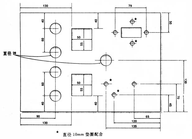
Figure 4 detailed dimensions of the chassis
Transistor differential amplifier is installed on the printed circuit board as shown in Figure 6. Please process according to the printed board drawing provided in this article, and install the above components. The transistors and capacitors on the entire machine are polar components and need to be identified and installed normally.

Figure 5 Power connection
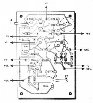
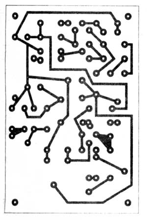
Figure 6 Printed circuit board component layout
Hybrid amplifier printed board
After making the above preparations, the assembly wire can be assembled according to the wiring pictures in Figure 3, Figure 4 and Figure 5 and the bottom view.
First fix the large components such as the electronic tube base, output transformer, power transformer, power switch and so on to the base plate, and then install the input and output sockets and the front-level printed board. Pay attention to the metal part of the component, the cold and hot ends of the input and output sockets, and the printed board to ensure reliable insulation from the metal chassis to ensure installation safety and to avoid the formation of noise interference due to the "ground loop". Necessary trouble. Please note that the power transformers T2, T3 and the output transformer T1, the filter capacitor C, and the four ceramic 8-pin valve sockets are installed on the outside of the bottom plate, and the power transformer T4 and the front-stage printed board are installed on the inside of the bottom plate. See the photo.
After installing the large parts of the machine, you can now start to connect the parts. Please refer to Figure 3, Figure 5 and Figure 6 for details. Please note that a shielded wire should be used from the input socket to the front panel, and it must be grounded at one point. From transformer T. The connection between the secondary end of the transformer T and the filament and the front printed board is with AC components. Please use double-core stranded copper-core plastic wires to make the transformer magnetic field around them have a self-cancellation effect. It is very beneficial for reducing hum.
Strict attention should be paid to the importance of the process and location of the grounding point of the common line (commonly known as the location) to improve the performance of the machine. The grounding point of each component (marked as CE in the figure) should be a separate lead. The negative terminal of the capacitor C3 is a point, which is a parallel star connection. Don't use the wrong method of connecting a wire to the bottom and each of them scattered on the metal base plate. This may cause a "ground loop" and reduce the signal-to-noise ratio. Similarly, the metal base plate should also be connected to the zero potential by a separate wire from the negative terminal of C3.
This machine is a hybrid of transistors and electron tubes. There are many large components. The power of the electric soldering iron may require 45W to 75W to be soldered. The printed circuit board and components of the transistor part are more delicate, which requires a 25W to 35W soldering iron. Perform welding.
After the installation of the whole machine, please carefully check the circuit carefully several times to avoid major losses after power-on. 1 There is a high voltage inside the machine. Please pay attention to the insulation performance. The bare joint of the high voltage part must be sleeved.
Seven, debugging

After completing the above installation process and checking and verifying it, we will start to debug the whole machine. Debugging requires a multimeter of 20kΩ / V or more, a screwdriver and then your golden ears. Tube amplifiers are much more convenient than transistor debugging, as long as careful operation is easier to complete.
The first step; measurement and approval of several key voltages. Several key voltages of this machine have been marked on Figure 2. To prevent voltage inaccuracy and burn out expensive tubes, please unplug 4 EL3 / t tubes from the tube base during the first test. When pulling and installing the electronic tube, be sure to hold the bakelite part of the tube base with your fingers. Gently shake and pull the left and right, and pay attention to the key slot. Plug in the power plug, turn on the power switch, the first step is to see if there are any abnormal conditions caused by poor component quality such as severe heating and bursting of components. If it is normal, you can check whether each voltage is consistent with the normal operation. Please check if the voltage of the electronic heater (filament) is 6.3V, and the grid-to-ground potential is -30V (the electron tube works in Class A, Class A and Class B, no grid current is generated, and it can be regarded as the input impedance is near It seems that the infinite resistance of the open circuit will not have a shunt effect in parallel with the external circuit). If the measurement result is normal, the next adjustment can be made. If the contrary is true, first, the DC potential of the collector of the front-stage differential tube is unbalanced to ground, which can be adjusted by adjusting the adjustable potentiometer PR1. Second, the collector potential is not -30V, which requires adjustment of R3 data. R3 is large, Ic is small, the absolute value of negative potential increases, R3 is small, Ic is large, and the absolute value of negative potential decreases.
During the adjustment, pay attention to that because the high-voltage filter capacitor stores high-voltage energy, before the adjustment after shutdown, a high-power resistor of about lkQ to 2kQ needs to be used to discharge c to ensure safety. After the above test adjustment is completed, Shut down. It's time to audition. Remember:
1. Connect the speaker load!
2. Temporarily solder open the connection point of T11 hot end and take the negative feedback resistor R7.
Plug in 4 EL34 tubes, no signal is input to the input terminal (Q1 base). Turn on the power switch, at this time, we will see that the heat of the electron tube (filament) slowly glows red after the power is supplied, and then there is a slight sound in the speaker. If the whole machine is well balanced, this When the sound is very small. If there is hum, you can adjust the moving piece of PR1 left and right to minimize the hum. At this time, you can input a low-volume signal for sound test. Note that since no negative feedback is added at this time, the open-loop gain of the whole machine is very high, and the sound is very loud. So be sure to lower the input signal level to avoid damaging the speakers.
If the amplifier you installed has passed the above steps, then you have completed 90% of the workload, and you can perform the last step of adding negative feedback.
You must be mentally prepared for this job. Because, the point of negative feedback is wrong if the primary and secondary phases of the output transformer are connected. At this time, positive feedback is formed, which is often called oscillation, and the loudspeaker will make a loud noise like a cow roar. If this is the case, you do n’t have to panic and shut down immediately. Just swap the connections between the cold and hot poles of the secondary side of the output transformer. Naturally, if everything is normal, and after adding negative feedback, your machine will be less noisy, and the music will obviously turn better. An amplifier using a well-known audiophile-grade tube was successfully produced. 1 Excited, you may wish to try the "blue two floors" and "saxophone. I believe you will be moved, there is really such a wonderful music in the world, really intoxicating 1

Follow WeChat

Download Audiophile APP

Follow the audiophile class
related suggestion
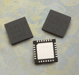
Avago Introduces New High Linear Power Amplifier Module Product Avago Technologies ...
The circuit is shown in Figure 1. The chip IC uses the LM1875 of the American NS company, which has a soft tone and low distortion (0.015% ...
The word "Monster" has both positive meaning and ...
When the output power of the digital power amplifier is greater than 50W, it is impossible to use only ...
If an "audiophile" is a group of people who are never satisfied with the sound and "loved the new and the old" with the audio equipment. Then just rely on these so-called "fever spirits" ...
First, the circuit principle and characteristics 1. Power amplifier part (see Figure 1)
There is a well-known saying in the Hi-Fi world that is "briefness first." This means that if ...
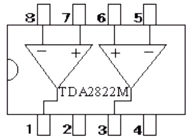
Simple and practical TDA2822M integrated power
TDA2030 is ...

STK465 thick film ...

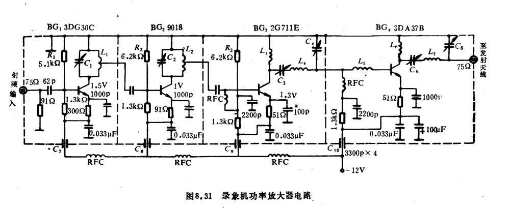
This RF power amplifier can output 2-3 channel signals, covering an area of ​​about one square kilometer, is ...
![[Photo] 15w RF power amplifier](http://i.bosscdn.com/blog/20/06/41/521040781.gif)
![[Photo] Broadband high frequency power amplifier](http://i.bosscdn.com/blog/20/06/41/520536801.jpg)
(1) 45-925MHz FM receiver head recently saw an introduction from "Electronic News" ...
![[Photo] 45-925MHz FM receiver](http://i.bosscdn.com/blog/20/06/41/5192132233.jpg)
Low frequency power amplifier
![[Photo] TDA2030 audio power amplifier](http://i.bosscdn.com/blog/20/06/41/5131012891.gif)
Looking at the Hi-Fi amplifiers currently on the market, the output power is 100W ...
![[Photo] Transistor 15W Class A Power Amplifier](http://i.bosscdn.com/blog/20/06/41/513102891.gif)
With the newly launched LM4651 and LM465 from National Semiconductor ...
![[Photo] 125W Class D Subwoofer Power Amplifier](http://i.bosscdn.com/blog/20/06/41/513100868.jpg)
![[Photo] Mark Levinson No. 30 ...](http://i.bosscdn.com/blog/20/06/41/513544752.jpg)
This article cleverly combines the electronic tube EL34 and the transistor (op amp), ...
![[Photo] 32W hybrid audio power amplifier](http://i.bosscdn.com/blog/20/06/41/513526493.jpg)
The pre-amplifier adopts a European-made TESLA brand low noise high cheek double transistor ...
![[Photo] Gallstone hybrid power amplifier using switching power supply](http://i.bosscdn.com/blog/20/06/41/513524776.gif)
"Simple" means the circuit of the amplifier is simple, making it easier, as long as the picture ...
![[Photo] Simple fool power amplifier](http://i.bosscdn.com/blog/20/06/41/513432946.jpg)
1. Description: & nb ...
![[Photo] LM386 low voltage audio power amplifier ...](http://i.bosscdn.com/blog/20/06/41/513417261.gif)
The Class A transistor power amplifier has a warm and sweet tone, which makes people tempted. But the temperature rise of Class A amplifier ...
![[Photo] Class A power amplifier using SAP15N / P audio pair tube ...](http://i.bosscdn.com/blog/20/06/41/513346769.gif)
The circuit is shown in Figure 5, ...
![[Photo] Using TDA7294 and 2SA1216 / 2S ...](http://i.bosscdn.com/blog/20/06/41/4233420295.gif)
'+ data.data.username +' '; dom + ='
Single-axis smartphone stabilizer is a pivoted support that allows the phone staying stabilized.
With a gyro-stabilized gimbal system, it keeps stabilized or steerable horizon with automatic calibration
to give you an unprecedented smooth shooting experience.

1axis smartphone gimbal are designed as pocket size, portable and easy to take.
You can carry it as easy as smartphone!


Wewow focusing on handheld stabilizer is a technology company which does R & D independently.
With Wenpod series product released, the company achieved the industry's praise and quickly became
the leader of the smart stabilizer industry.
Our service
1. Reply to you within 24 hours.
2. Already sample: within 1-2days.
3. Shipping date: within 24 hours once get the payment.
4. 12 months warranty.
5. After-sales service, solve within 3 working dates.
If you have any questions, please contact with us directly.
Wewow appreciates domestic and international business relationship!
Single-axis Smartphone Stabilizer
Single-Axis Smartphone Stabilizer,Professional Single-Axis Smartphone Stabilizer,Smartphone Stabilizer With Single Handheld,Single-Axis Smartphone Gimbal Stabilizer
GUANGZHOU WEWOW ELECTRONIC CO., LTD. , https://www.stabilizers.pl