
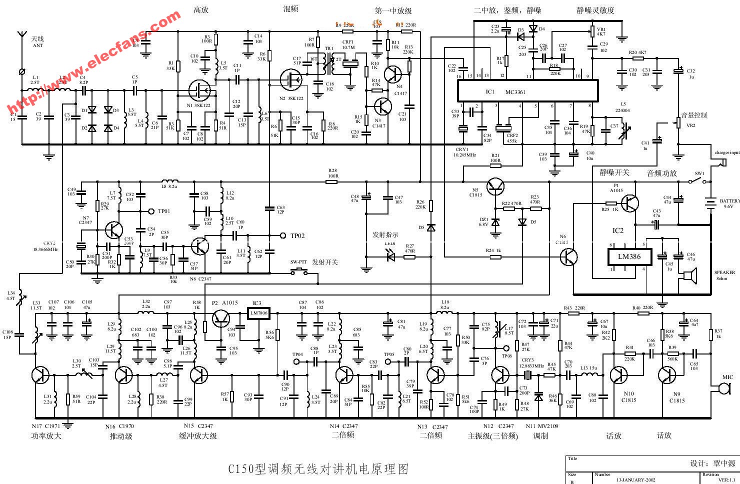
Wireless intercom circuit diagram
The principle of wireless radio production 30.275MHz FM 1. Main technical indicators:
1. Frequency: 30.275MHz
2. Modulation method: frequency modulation
3 Frequency deviation: 5KHz
5. Communication method: same frequency simplex
6. Power supply voltage: 9.6V 10% (8 nickel-cadmium rechargeable batteries, negative electrode grounded. Some models have 6 batteries)
7. Current consumption:
Squelch Waiting: Receiving below 10mA: Short-range transmitting below 150mA:
Remote launch: below 0.7A
8. Carrier frequency output power: 2w
9. Receiving sensitivity: below 1.0uV (signal to noise ratio above 12dB)
1 0. Squelch sensitivity: 0.5uV
11. IF frequency: 455 KHz
12. Audio distortion power: greater than 200 nlw
1 3. Volume: 125 x 55 x 30 mm
14. weight:
Second, working principle The whole machine is composed of two parts: receiving and transmitting. The two parts are independent of each other except the antenna and impedance matching circuit.
1. The high-frequency radio signal received by the receiver through the antenna filters the interference signals outside the frequency band through the low-pass filter composed of L1, L2, c1, c2, and c4, and sends it to D1, D2, and L3 through c6 to form a frequency selection circuit The resonant frequency of this frequency selection circuit is 30.275MHz. The carrier frequency signal sent by the intercom is selected, and other interference waves are filtered out. It is sent to the cascade high-frequency signal amplifying circuit composed of N1 and N2 via c7 for high-frequency amplification. This cascade high-frequency signal amplifying circuit has the advantages of high gain, stable operation, and the need to use neutralizing capacitors. N1 forms a common-emitter circuit , N2 is connected into a common base circuit, common emitter circuit has the advantage of high gain, and common base circuit has the characteristics of stable operation, the high frequency signal amplified by N1, N2 is composed of L4, c9, T1, c12 double tuning loop again After frequency selection, it is sent to the 16-pin internal mixing stage of ICl (MC3361) via c16 for mixing.
N3 and CRY1, L5 and other components form a local oscillator. L5 and the corresponding loop capacitor resonate on the third harmonic of 10.243MHz, that is 10.24333x3 = 30.730MHz, which is 30.275MHz (10.0917 triple frequency, ie 10.0917MHzx3 = 30.275MHz) is higher than an intermediate frequency of 455kHz (that is, 30.730-30.275 = 0.455MHz), and the local oscillator signal is also sent to the first pin of Icl for mixing within Icl.
Ic1 (Mc3361) is a narrow-band FM receiver dedicated integrated circuit, which contains an oscillator, mixer, high-gain limiting IF amplifier, discriminator and active filter, noise suppression trigger circuit and audio amplifier circuit. Its limiting sensitivity is 2uV, it is the main gain stage of the whole machine, and the gain of the intermediate amplifier can reach 65dB.
The 455kHz intermediate frequency signal obtained by internal mixing in Ic1 is output by pin 3 of Icl, and the intermediate frequency signal is selected by ceramic filter cRFl, and other harmonic components are filtered out. The selected intermediate frequency signal is input by pin 5 of Icl, inside Icl Carry on the high-gain intermediate frequency amplification, and finally demodulate the audio signal by the frequency discriminator, which is output by pin 9 of Icl.
The signal output from pin 9 is routed to c30, R1 3 and c32 to form a de-emphasis circuit. After de-emphasis and filtering, it is sent to Ic2 through potentiometer VRl for audio power amplifier, and then the speaker is driven to sound. The frequency of the active filter of the active filter is amplified and output by pin 11 of Icl. The voltage doubling detection is performed through D3 and D4 to control the internal noise suppression trigger circuit. A control level is output at pin 13 to control the conduction of N4 and N5. And cut off, so that the power supply of IC2 is controlled to achieve the purpose of noise suppression. We know that the sensitivity of the FM receiver is very high. When no signal is received, the horn will emit extremely strong noise, and once the signal is received, its signal-to-noise ratio is very high, and the main spectrum of noise is distributed in 1 0-25kHz range, the frequency range of the audio signal is between 100-3000Hz, we can use a special filter to select this noise signal, after detection into a DC component, and then through an electronic switching circuit A circuit can be controlled to achieve the purpose of noise suppression, so that when the receiver does not receive the signal, the speaker will be silent to eliminate the annoying noise. Once the signal from the intercom is received, the amplifier circuit can be automatically opened to contact. At the same time, setting the noise suppression circuit can also achieve the purpose of power saving.
N11 constitutes a regulated power supply, and the regulated output depends on the value of Dzl. Dzl selects 6.2V, and the regulated output is about 5.6V. N11 is also a switching transistor for transceiver, and N9 is a power switch for the transmitter. When the sw_PTT switch is pressed, D6 is turned on, N11 is turned off, the receiver loses voltage and stops working, N9 is turned on because of an error, the power is supplied to Ic3 through N9, and the transmitter front stage receives power and starts working. Therefore, this transceiver circuit is also called an electronic PTT switch, which is a new circuit not found in other amateur radios. Its advantage is that it can use the micro switch to control the large current, making the circuit work more reliable. Although the N7 and N6 of the transmitter stage are also connected to the common power circuit, when in the standby state, it is cut off because it cannot get the base excitation, so the transmitting part of the radio is not working when it is in the standby state.
2. Transmitter The transmitter consists of a voice amplifier, a main vibration stage, a buffer amplifier stage, a booster stage and a final power amplifier stage.
The voice signal is amplified by a two-stage audio amplifier composed of N1 3, N14, and a high-frequency filter is formed by c74, c71, c70, L1 3 to filter out high-frequency components, to prevent the high-frequency signal of the oscillator from interfering with the work of the voice amplifier The voice signal is also pre-emphasized and sent to the varactor diode Dc via c70 to achieve frequency modulation.
The main vibration level is composed of N1 5, cRY2 and peripheral components. Its oscillation frequency mainly depends on the operating frequency of cRY2. In this circuit, cRY2 selects 10.0917MHz (because 10.0917x3 = 30.275MHz), and its triple frequency signal is generated by T5. , C64 frequency selection loop frequency selection (that is, the transmission frequency of 30.275MHz), and from T5 coupling to the buffer amplification stage.
The carrier frequency signal is amplified by a buffer amplifier formed by N10. T4 and tank capacitor c61 are also resonated at the third frequency multiplication (ie, the transmission frequency is 30.275MHz) to filter out other harmonic components. N7 is the driving amplifier stage, which is the amplifier stage Provide sufficient driving current, through c55, c51, L8, frequency selection and matching coupling to the final power amplifier stage N6 for power amplification, N7, N6 are working in the Class C amplification state, and their operating points depend on R23 and R21, because the second harmonic component output from the Class C amplifier is very large, the fundamental wave component must be selected by the Lc frequency selection circuit. The driving circuit is selected by c55, c51, L8, and the power amplifier circuit is composed of C48, C47, L6 The series resonant circuit selects frequency. Finally, a low-pass filter composed of L1, L2, C1, C2 and C4 performs frequency selection and impedance matching on the carrier frequency signal. The carrier frequency current is transformed into electromagnetic waves by the transducing element of the antenna and radiated into the air.
The function of the R7 and D3 branches in the circuit diagram is that at the moment of transmission and reception conversion, due to the energy storage function of the receiving part of the capacitor, the work of the receiver is not immediately terminated, and the 13 pin of Icl fails to change from high level immediately When it becomes low level, Ic2's work fails to stop working immediately. In this way, at the moment of transmission and reception, a short-time transmission and reception noise will be emitted from the speaker, which makes people sound extremely uncomfortable. Therefore, when the power is switched to the transmitting circuit Through R7, D3, this branch is added to the 12 pin of Icl, making the 1 3 pin of Icl immediately become low level, N4, N5 cut off, Ic2 stops working to eliminate the conversion noise.
Third, the production process and the selection of components for the success of the production of radios, in addition to human factors such as theory, experience, accurate working frequency and correct debugging methods, there is also a key component quality problem, that is, one of the components is of poor quality , May cause you to struggle through several sleepless nights, and may not be successful. According to the author's experience of making more than ten walkie-talkies, the receiver's sensitivity is most closely related to N1 and N2. In addition to N1 and N2 being related to their high-frequency characteristics, another important parameter is their noise figure. The common s9018 and other cheap high-frequency tubes have large noise figures, making it difficult to achieve the expected sensitivity.
In addition to N1 and N2 high-frequency triodes, CRFl ceramic filters have a great influence on the sensitivity of the whole machine. Genuine components should be used. It is best to use five-terminal ceramic filters because its frequency selection characteristics are better than three-terminal filters. . High-frequency ceramic capacitors should use components with low leakage and good thermal stability.
In addition to the mentioned components, ordinary components can be used for other components, and they can be used in amateur conditions. According to the author's experience, those non-main components have a slight influence on the receiving sensitivity.
Because ICl is a dedicated narrowband FM receiver chip, performance is generally guaranteed. The best quality is counted by the products of MOTOROLA, as shown in the picture. Secondly, MALAYSIA also produces well. It is worth mentioning that the author got several pieces of Made in China MC3361 chip, through the use of German signal generator (frequency in 50MHz range accurate to 10Hz, output resolution up to 0.01uv) and other instrument comparison experiments, domestic The sensitivity of the product is basically the same as that of MOTOROLA. So ICl's performance parameters don't need to be considered at all.
The resistor can be selected from general carbon film resistors, and there is no special requirement for accuracy. 1 / 8W and 1 / 16W are acceptable.
Of course, the two-way radio hopes that the smaller the size, the better, and amateur production is no exception, so the components should use ultra-small components as much as possible.
The components of the transmitter part are also the key part of the success or failure of the production. The most influential ones are the transistors of the driving level and the power level. The author has tried several tubes, the models are 2sc2078, but the origin is different. Earlier I used a common tube (viewed from the outside, the silk screen is not very clear, and the process is also poor), using a 9.6V power supply, excluding other factors, the power can not be adjusted to 2W anyway, the emission level current is only more than 400mA a little. I thought that the frequency was not adjusted to the third harmonic of 10.0917, which might be the fourth or fifth harmonic. Afterwards, it was calibrated with an oscilloscope and a frequency counter, and it was inferred that the quality of the power tube was not good. Power supply, the current soared to nearly 0.8A, the power meter measured 2.6w. This shows that the quality of the final power tube directly affects the power output, which will obviously affect the talk distance of the intercom.
In addition, is the higher frequency of the high-frequency power tube better? For example, some enthusiasts are willing to use the VHF band tube up to 175Mt {z such as 2SC1971, 2SC1972, etc., I do not recommend the use of high frequency power transistor, the first is Because such pipes are quite expensive. The second is that the frequency is too high, the circuit is easy to self-excitation, not easy to debug. The author encountered such a problem, using 2sc1969 in a desktop computer, the circuit works quite normally, and the power can also reach about 8w, which has been used for a long time. It was later changed to 2sc1971, but the circuit was seriously self-excited. It took a lot of effort and took a lot of measures to solve it. The actual output power is basically the same as 2SC1969.
In addition to the transistor, the frequency of the quartz crystal must be selected accurately. The frequency deviation will obviously affect the call distance. We will explain the debugging part. The number of coil turns in the high-frequency part has been marked in the circuit diagram. It can be wound with φ0.17-0.35mm enameled wire on the high-frequency magnetic core or the mid-peripheral magnetic core. The diameter of LI and L2 wires needs to be larger because they are also For the transmission circuit of high-frequency power, the intermediate frequency discriminating coil can be replaced with a ready-made 455kHz (or 465kHz) mid-cycle.
There are no special requirements for other components, and the selection of resistance and capacitance parts is the same as that of the receiving part.
four. Assembly and debugging The assembly method of the radio is similar to the assembly method of the general radio. It should be noted that the pins of the components should be as short as possible in order to adhere to the printed board, and the connection to the antenna base should also be as possible Is too short, otherwise the output power will obviously decrease. If the output end is far away from the antenna base, generally more than 1Omm should use 50 coaxial cable connection.
The layout of the components and the wiring of PcB are the key to amateur production. If you walk around randomly, many unforeseen problems will occur during debugging, crosstalk, coupling, and self-excitation between stages. These problems may not be solved by other methods. Finally, I had to walk through PcB again, reassemble, re-debug, and take many detours. The principle of PcB wiring of the high-frequency board is roughly: each stage should be placed as much as possible (one area), and the circuit that works at the same time, the high-power output stage should be as far away as possible from the small-signal circuit, and between stages The ground wire surrounds the structure, cleverly using iron shields such as the middle circumference to isolate the inter-stage circuit. If possible, small signals (especially the receiving part) also need to arrange the shield and reliably ground. It is very important that the intermediate frequency resonance coil T2 must be close to the 8th pin of Icl. If the trace is too long, the sensitivity will be very low and may cause other self-excitation problems. For the same reason, the intermediate frequency filter CRF1 must also be close Rely on IC1. PCB layout must not ignore this.
The layout of PcB components should not simply pursue beautiful and neat, but should be based on the principle that they can work reliably. Of course, it can not only ensure the reliable and stable operation of the circuit, but also make the component layout beautiful and beautiful, even a master!
The following picture is the PcB wiring diagram of one of the walkie-talkies of the author. Of course, it is the work after N times of modification and perfection. If you are interested, please take a look. It is for reference only. I believe it is helpful for beginners.
After the assembly of the whole machine is completed, it should be carefully checked for errors before it can be commissioned. The DC operating points of these four circuits do not need to be adjusted. Their working status has been fully guaranteed during design. The voltage point can be checked again, which is similar That's it. The debugging of wireless walkie-talkies generally requires the use of instruments to ensure their performance indicators. The instruments required for adjustment are generally the following:
1. High frequency signal generator (such as xFG-6 type)
2. Oscilloscope (such as VP52 04 type 40MHz)
3. Digital frequency meter (such as cFc-8450 type, 0-1000MTIz)
4. Power meter (such as Gz-3 type)
5. DC power supply (such as wYJ-30V / 5A type)
6. Multimeter (such as MF-47 type, if there is a digital meter Fluke-87 and other high-end instruments best match)
7. Field strength meter (self-made)
Of course, there is a frequency sweeper. A complete instrument will bring great convenience to debugging, and at the same time, it can ensure the performance index of the whole machine.
For general amateurs, the above instruments are generally not available, but frequency meters are indispensable. Here we will combine the characteristics of amateurs and professionals.
Introduce the debugging method of FM wireless intercom in detail.
1. The debugging sequence of the transmitter is generally as follows: first adjust the oscillation level, frequency doubling level, push level, and final power amplification level. Finally, adjust the voice amplifier circuit.
Connect an ammeter (3A range) to the total power supply circuit, turn on the power, and press the launch switch. If the current value is greater than 1.5A at this time, it indicates that there is a short circuit in the whole machine. The fault should be eliminated before restarting. Although the machine can work safely with a 3.6V power supply, do not use too high a power supply voltage at the beginning to prevent burning the final power tube when the circuit is detuned. Generally, the power supply voltage of 8.6V can be used to complete the debugging. . Note that the final power tube needs to be equipped with a sufficiently large heat sink.
First determine whether the main vibration level is oscillating. The method is to measure the emitter voltage of N1 5 with a multimeter, which is normally about 2V. If it oscillates, the voltage should be as high as the base voltage, or even higher than the base voltage. It is an obvious characteristic of the oscillation of the oscillation circuit. There is no oscilloscope in amateur production. You must master this principle. It is very useful for debugging. An oscilloscope can be used to observe the collector of N1 5 with an oscilloscope. The waveform shown in Figure 3 will be observed. If the amplitude of the waveform is too small, T5 can be adjusted. Generally, the waveform can be called out. If the waveform is not observed, it means that the circuit has If the fault (generally T5 is badly wound), the cause should be found to eliminate the fault. When the circuit is not vibrating, it will work in a linear amplification state, and the emitter voltage will be about 0.65v lower than the base voltage.
After confirming that the circuit starts to vibrate, use a frequency meter probe to connect to the collector of N15 to measure the oscillation frequency. Normally it should be 30.275MHz (or 10.917MHz, depending on the adjustment of T5 and the connection of the frequency meter, the measured frequency is 10.917MHz It is because the fundamental frequency of the crystal is measured, and the measured value is 30.275MHz is the third harmonic). If there is an error, the capacity of c69 should be adjusted until it meets the requirements. The resistance value of R32 and R33 can also be changed. To adjust, but not to change too much their resistance, can only be adjusted within a small range. It is required that the carrier frequency frequency error should not be greater than 1.5kHz. At this time, you can use an oscilloscope to observe the T5 secondary waveform and adjust the T5 magnetic core to make the third harmonic waveform clear, glitch-free, and the maximum amplitude, but it must be based on the principle of stable waveform , Switching power supply can start normal vibration several times as well. Then observe the collector of N7, adjust the magnetic core of T4 to make the best waveform, the largest amplitude, close to the sine wave, see Figure 4. A 50 Ω dummy load is connected to the antenna, a low-voltage small-power small lamp can be connected in series, and on the dummy load slightly larger than 50Ω, the brightness of the lamp can be observed to judge the output power. Adjust L8, L6, L1, L2 separately to make the maximum output power, the maximum amplitude of the sine wave, and the waveform is good. See Figure 5. When speaking into the microphone, the waveform does not change, and the current value is about 0.75A. If there is no oscilloscope, a self-made field strength meter (refer to Figure 6) can be placed next to the antenna to monitor, adjust L8, L6, L1, L2 to make the field strength meter placed next to the antenna indicate the best.
One thing to note: when adjusting at the resonance frequency, the current indication is the smallest, but when adjusting T5 and T4, if you deviate from the resonance point, the amplitude will decrease and the current will also decrease. This must be treated differently when adjusting. Generally it is Adjust L8, L6, the greater the current, the better, the greater the power, and the current should be appropriate when adjusting L1, L2, after repeated debugging, to ensure that the frequency is accurate, the maximum output power.
Sometimes, the power will not be adjusted much during debugging, and the current value can not reach 0.75A. At this time, it should be considered whether the quality of the power tube and the driving tube used is reliable, and generally good quality transistors should be selected. The quality of the final power tube directly affects the power output.
The debugging should be based on the premise of stable circuit operation. Do not blindly pursue the factor of high power output and ignore the stability. At the same time, the power supply voltage should be reduced to 7V or increased to 12V. The circuit should be able to work reliably and stably.
Debugging of the voice processing circuit: In fact, as long as the components are reliable at this level, the circuit does not need to be debugged. If you want to check, you can input a 1kHz / 50mV audio signal at the microphone input, and use a millivoltmeter or oscilloscope at the N14 collector For measurement, there should be an audio voltage of about 2Vp-p.
2. Under the debugging conditions of the receiver, the final total tuning of the receiver can use the adjusted transmitter as the signal source for joint debugging. There is no frequency meter under amateur conditions. Use the transmitter signal to adjust. If the transmission frequency differs by a few kHz, the receiver also follows the deviation by a few kHz. It has little effect on production. Amateur production is completely acceptable, but the performance index is slightly lower. Generally, it doesn't need too much power for distance debugging, the signal source radiation is too strong, and it is difficult for the receiver to adjust to the optimal point, that is, it is difficult to adjust to the resonance point. It is appropriate to receive the signal of the transmitter with a little noise.
First, measure the emitter voltage of N11 with a multimeter. The normal voltage should be 5.6V. For safety reasons, the working voltage of each point of the circuit can be measured. For the value, refer to the circuit diagram. Generally, it should be close to the value in the circuit diagram. Otherwise, the circuit still has problems. This gives a general understanding of the working state of the circuit.
First determine whether the local vibration level is oscillating. The method is similar to adjusting the main vibration level of the transmitter. Use a frequency meter to measure the collector of N3. The frequency should be 30.730MHz. If there is an error, you can add a few at both ends of CRYl. The capacitance of P-20P makes the frequency meet the requirements. Similarly, the frequency error should not exceed 1_5KHz. There is an oscilloscope. You can use the oscilloscope to observe the waveform of the T3 secondary. Adjust L5 and T3 to make the waveform best and the maximum amplitude reaches 80mV-100mVp-p.
Turn off the squelch potentiometer to make the horn appear noise, adjust the magnetic flux of T2 to maximize the noise in the horn, you can also use an oscilloscope to observe the waveform at both ends of the horn, adjust T2 to make the noise waveform (the waveform should be disordered) The largest, symmetrical waveform.
Set the signal generator to: the frequency is 30.275MHz, the frequency deviation is 5kHz, the modulation frequency is 1kHz, input this signal at the antenna end, gradually increase the signal level, generally you can hear the audio sound in the la bar at more than ten uV, Adjust T2, T1, L4, L3 to maximize the sound, gradually reduce the signal level, then adjust the above adjustable components, if necessary, adjust L5, T3 to maximize the audio sound, the best sound quality, generally can adjust the receiving sensitivity To 1.0uV, of course, there is no noise at this time, it refers to the receiving sensitivity at a signal-to-noise ratio of 12dB.
Remove the signal source, slowly adjust the squelch potentiometer to make the noise just disappear, reduce the level of the signal source to 0.5uV again, and connect the signal to the antenna end again. At this time, the squelch door should be able to open the receiver It should be able to receive the signal.
If the above sensitivity can be adjusted, the receiver is basically adjusted. Exchange the two machines and adjust their transmission and reception parts. The next step is joint debugging.
3. Joint debugging will complete the debugged machine, install it in the case, connect the battery, connect the antenna, LED and microphone. Here we need to declare that the antenna plays a decisive role in the communication distance. The amateur homemade antenna does not adjust the transmission. It is difficult to ensure the performance of the receiver. It is best to select the finished antenna first if possible, and it must be in the 30MHz band, otherwise the call distance will be difficult to meet the design requirements. Use one as a transmitter (the transmitter should remove the unstaged power level to reduce the RF power), and the other as a receiver, open the distance between the two units until the signal is just received, fine-tune the receiver T2, T1, L4, L3, L2, L1 make the received signal the strongest, the best sound quality, and then open the distance between the two machines, and then adjust, until the distance between the two phones is the farthest, it should be noted here, generally only Can be fine-tuned, because after the above adjustments, the frequency is generally adjusted more accurately. If you make more large adjustments, sometimes you can only adjust more and more chaos.
Connect the unstaged power tube of the transmitter and the local antenna. Generally, you only need to fine-tune L1 and L2 to maximize the indication of the field strength meter beside the transmitter. Because the matching network cannot be adjusted well, it will seriously affect the transmission power. , That is, the transmitted electric power is large enough, but the electromagnetic wave energy radiated from the antenna is much smaller, because the carrier frequency current is not fully delivered to the antenna, but part of the carrier frequency current returns to the power amplifier in the form of standing waves Obviously, the efficiency of this circuit will be greatly reduced, and the distance will be greatly shortened.
The simplest and most reliable method is to use the field strength meter to monitor next to the intercom. The transmitter debugging is subject to the maximum indication of the field strength meter. Based on years of practical experience, do not underestimate the self-made signal field strength meter. It is very useful in the entire production process. If you think that the instrument must be a finished product, or if you import high-end instruments to debug the device, this is a common misunderstanding. You must fully believe that the simple but realistic instruments you make can rely on them to also make and debug radios with excellent performance. This does not violate the original intention of the hobby.
During joint debugging, the power of the transmitter should be as small as possible, so that the receiver can be adjusted accurately, and the distance should be gradually adjusted for debugging. Generally, after the transmitter is adjusted, it is not appropriate to adjust the coil of the transmitter. Otherwise, the state of the transmitter may be adjusted. Sometimes, when adjusting L1 and L2, the contradiction between the transmitter and the receiver may sometimes occur. At this time, care should be taken. The receiver is suitable.
The above debugging methods are for reference only. In actual debugging, you may encounter many problems. You should continue to summarize in practice and make debugging records. Amateurs have a common problem. Your own work may do a lot. I do n’t have my own written things, I do n’t know what to do if I have problems, or there is no basis to check, because there is no record, it is strongly recommended that amateurs develop a habit of taking notes (recordings) diligently. The first is achievement Second, once there is a problem, it is convenient for you to trace and analyze. As long as you carefully analyze the working principle of the circuit and master the essentials of debugging, you will be able to make a wireless radio with good performance.
four. About the call distance The wireless walkie-talkie works in the ultra-short wave band, with high frequency and poor diffraction ability. It mainly depends on the direct wave, and the propagation distance is mainly within the line of sight. Since the surface of the earth is curved, assuming that there are two people with a height of 1_8m in a flat area of ​​the plain, then they can see each other ’s head at a distance of about 10-12 kilometers, (we refer to the distance of sight, Not really visible to the naked eye, similar to looking up with a telescope), because the wavelength of the radio wave is very short, the wavelength of the radio wave of 30MHz is 10m. The small buildings on the ground have a significant impact on the radio waves, such as mountains, trees, buildings, high-voltage transmission lines and other media. In order to induce currents in the electromagnetic waves, they must lose energy, plus different degrees of interference in the air Radio waves, this will reduce the call distance.
In this case, if they use a walkie-talkie in the 30MHz band, equipped with a 0.15m normal mode helical antenna, which is 10-12 kilometers apart, it is difficult to make a successful call. Even if it is within the line of sight, it can not be clear .
The actual call distance is as follows:
1. In the city, there are many buildings, the electromagnetic environment is polluted, and the radio interference is strong. The communication distance can only be about 1 km, and the rod antenna can only be about 2 km.
2. If you board a 3-4 floor, use a whip antenna, or use the whip antenna in the above-mentioned flat area, the communication distance can reach 3-5 kilometers.
3. One or both parties holding a walkie-talkie stand at a height of 10-20m, or use an outdoor antenna, equipped with a 50 Q coaxial feeder, and there is no high mountain blocking, which is equivalent to increasing the line of sight, and the call distance can reach 5-10 kilometers .
4. Therefore, it is worth exploring how the user can choose the location of the call, or if one party is equipped with an outdoor antenna to give full play to the effectiveness of the equipment in his hand and increase the call distance.
5. As far as walkie-talkies are concerned, the sensitivity of the receiver has a significant impact on the talking distance. However, increasing the transmission power does not significantly increase the talking distance. The transmission power is increased by 10 times, and the talking distance may sometimes be only double.
6. In addition, electromagnetic waves in the 30MHz band can sometimes be reflected by the ionosphere, so at night or at the turn of spring and summer, you can receive radio signals from tens or even hundreds of kilometers away. This is not surprising, but the signal will not be very stable.
7. In the city, various industrial electromagnetic interference is quite serious, so the walkie-talkie in the 30MHZ frequency band is more suitable for rural areas with less interference. Qualified urban enthusiasts can also experiment in the suburbs, the effect will be better.
8. Interphones are generally equipped with local antennas (that is, normal mode helical antennas) for short portability. The length is short, the gain is low, and the communication distance is generally not far. In order to achieve long-distance communication, 0.5m to 1.0m should be equipped if possible. The bottom of the antenna is a pull rod antenna. The antenna with a sense of pulling rod at the bottom of 0.5m to 1.0m can be self-made. For the method, please refer to the following information.
5. Self-made 30MHz walkie-talkie antenna
1. Normal mode helical antenna walkie-talkies are generally shorter than normal mode helical antennas, with a length of only 12-16cm. It is insulated from each other in an insulating skeleton (can be a hollow structure with a diameter of about 11mm, such as polypropylene plastic rods, etc.) The metal wire (such as enameled wire) is evenly wound on the skeleton and the antenna base is added. If the length is 16cm, the number of coil turns is about 120T, if the length is 12cm, the number of coil turns is about 155T, specific The debugging method is:
Connect the wound antenna (about ten more turns) to the walkie-talkie, put a strong meter next to it, press the transmit switch, and start from the top of the antenna, cut the coil one by one round until the field strength meter indicates the maximum It is the resonant state of the antenna. At this time, make some fine adjustments to the tension state of the antenna, so that the field strength meter indicates that the antenna is tightly wrapped with insulating tape.
There is an obvious characteristic when the antenna resonates. The human hand is close to the antenna and almost touches. The wire on the top of the antenna will emit a strong spark (if the power of the intercom is large enough, this phenomenon can be felt at about 3w), available The hand clearly felt it. If the power of the walkie-talkie reaches 3w-5w, there will be a noticeable burning sensation in the hand. However, the power of the intercom is too large, it is not recommended to use this method for testing, because it may cause harm to the human body! This must be cautious in the experiment!
2. Bottom plus sense antenna The method of making the bottom plus sense antenna is to put a hollow insulating skeleton on the antenna base, the long reading is about 50mm, the diameter is 10mm, and then put a 0.5m long rod antenna on the top of the insulating skeleton, The skeleton is wrapped with a 0.5-0.7mm magnetic envelope wire around 34T, and the telescopic rod antenna is used to determine the number of coils to increase or decrease. When the antenna is fully pulled out, the field strength meter indicates the maximum and the coil is fixed.
When the bottom rod antenna is not fully pulled out, the gain is relatively low, because the antenna is not matched at this time, but when the antenna is completely pulled out, the antenna is in resonance and the gain is higher than the normal mode helical antenna. , So the call distance is also relatively long.
3. Central plus sense antenna There is also a middle plus sense antenna. The principle and manufacturing method are similar to the bottom plus sense antenna, except that the plus sense coil is placed in the middle of the antenna. Interested friends can also experiment.
4. 1/4 wavelength Brown antenna (outdoor antenna)
There are many types of outdoor antennas, which are relatively easy to make. The gain is also higher than 1/4 into the antenna. If it is made well, the gain can reach 3-5dB. The production method is: take 4 aluminum tubes with a length of 2.5m. If there is no aluminum tube, it can be replaced by ordinary wire, which is slightly less effective. One of them is placed vertically as the main vibrator, and the other three are 120 degrees from each other and are evenly distributed from the vertical direction at 60 degrees. As the radiating vibrator, the main vibrator and the radiating vibrator need to be insulated. The core of the 50-ohm coaxial cable is connected to the main vibrator. The ground network is connected to the radiating element, and the height is 15m. The outdoor antenna has a higher gain and no obstructions. Therefore, with the outdoor antenna, the talk distance of the intercom will be greatly increased. The antenna of the handheld is shorter, but the The power is relatively large, usually up to 10 w_15w, which can just make up for the shortcomings of the low gain of the handset, and the power of the handset is generally small, but the outdoor antenna is used in the machine, and the higher gain can also make up for this deficiency, so The quality of the conversation between the two computers and the handheld unit network is basically the same.
6. About the secondary frequency conversion technology
[1]. These circuits are single-channel walkie-talkies. The working principle of the double-conversion walkie-talkies is basically similar. For example, F36 is the double-conversion walkie-talkie circuit. It is easy for fans to see the similarities and differences of the circuits. On the basis of the addition of a level of the intermediate amplifier circuit and the second local oscillator stage, other circuits are similar.
The second frequency conversion is designed for higher gain and sensitivity of the radio and more stable operation. We know that the gain of a single-stage amplifier circuit cannot be infinitely increased by increasing the number of amplification stages to increase the gain. Because the gain of a single-stage circuit is too high, it will inevitably bring crosstalk and self-excitation problems between stages, and the work becomes unstable. It even becomes non-functional. Double conversion can better solve this problem, because the amplifier circuit is divided into multiple stages, different stage circuits amplify signals of different frequencies, and the interference between the stages can be overcome by notching, filtering, etc., making each The level circuits can work stably and reliably, and the total gain can be made very high. Like the short-band (or VHF) 30-150MHz, the receiving circuit first performs high-amplification, the gain is set to about 10-20db, and then the frequency is converted to the first intermediate frequency such as 10.7MHz, and then the gain is about 10-15dB first intermediate frequency amplification Then, the second frequency conversion stage performs second frequency conversion to generate a 455kHz second intermediate frequency signal, and then performs a high gain mid-amplifier of about 65dB, so that the gain of the entire circuit can be made very high. The walkie-talkie of the double frequency conversion circuit is very easy to achieve 0.2-0.5uV. Such high receiving sensitivity is the key to improving the talk distance of the intercom.
It is worth mentioning that the sensitivity of the double conversion is as high as 0.2uV, and even some professional machines (such as TK208, T: K308, TK378) can reach a sensitivity of 0.16uV. With such high sensitivity, the noise factor of the high discharge tube appears very Importantly, the transistor is generally not selected, but a double gate field effect tube with low noise coefficient and high impedance is used for high frequency amplification, which can be seen in the C36 circuit diagram.
[2]. The four circuit diagrams that my friend downloaded this time are circuits designed by the author for many years with reference to other professional, amateur intercoms, various radio receiving equipment, comprehensive performance and amateur self-made factors. According to the author's experience, it is too "amateur" Circuits, performance is not guaranteed, the call distance is very short, and audiophiles are not addicted to playing. Even if it is done, there is not much sense of accomplishment. As the saying goes, it is not fun. This is one of them. Secondly, if the circuit is too professional, it needs too many components, the circuit is too complicated, and the components are difficult to buy. The equipment required may not be affordable by amateurs. The assembly and debugging are complicated. Only the enthusiasm for doing it is not available. Self-made material conditions can't be played.
[3]. For multi-channel walkie-talkies, the low-end circuit is composed of multiple groups of crystals to form multiple channels, which are switched by mechanical or electronic switches. The more advanced circuits are implemented using phase-locked loops and frequency synthesis techniques, such as dedicated ICs such as Mcl45152 and uPB569C. More high-end machines use a microprocessor to synthesize and switch frequencies, such as the uPD7514G microprocessor of the first-generation c450. The use of these circuits naturally makes the performance of the machine much superior, but amateurs are required to be proficient in digital circuit and even microprocessor programming and development skills in addition to mastering radio technology. This is not what most amateurs can do.
[4]. The circuit of the desktop and the handheld is basically the same, but only one more power amplification stage is added at the final stage. The 30MHz frequency band can be selected from transistors such as 25C1969 (TO-220) or 25C1945. The output power can reach 10-15w with good debugging. Of course L1, L2 Need to use a larger wire diameter winding.
[5]. The intermediate amplifier circuits of these four circuits all use the narrowband FM receiver IC Mc3361. In fact, there are many circuits that implement the intermediate amplifier function, such as TKl0487M. There are more than ten products of MOTOROLA Company, such as MC3357, MC3359, MC3362 , MC3363, MC3367, MC3371, MC3372. MC3363 It integrates all circuits including almost all double conversions placed high. I have also made two of them.
Seven. Discussion on hobby spirit [1].这四份电路个人认为还是比较适åˆä¸šä½™çˆ±å¥½è€…自制的电路,所有的元件都容易获得,所需的仪器设备åˆä¸å¤šï¼Œåªæ˜¯ä»ªå™¨å¤šä¾¿äºŽè°ƒè¯•ï¼Œè¾ƒæ˜“æˆåŠŸç½¢äº†ï¼Œä½†æ²¡æœ‰ä¸“用的仪器设备ä¸ç‰äºŽå°±åšä¸å‡ºæ¥ã€‚笔者åšç¬¬ä¸€å°å¯¹è®²æœºæ—¶ï¼Œä»…ä»…å…·å¤‡ä¸€ä¸ªä¸‡ç”¨è¡¨ï¼Œåœºå¼ºè®¡è‡ªå·±åˆ¶ä½œï¼Œä¸€æ ·èƒ½åšå‡ºæ€§èƒ½è¿˜ä¸é”™çš„对讲机,具体的å‚æ•°æŒ‡æ ‡æ— æ³•çŸ¥é“,从通è¯è·ç¦»æ¥è¡¡é‡ï¼Œåœ¨å¼€é˜”地,使用法å‘模螺旋天线,åŒæ ·å¯è¾¾åˆ°3—4kmçš„è·ç¦»ã€‚这就说明,专用设备ä¸æ˜¯æœ€ä¸»è¦å’Œå¿…须的,最主è¦çš„是自己的爱好和工作çƒæƒ…。相å,没有专用设备å¯èƒ½ä¼šèµ°å¾ˆå¤šå¼¯è·¯ï¼Œä½†ä¹Ÿå¯ä»¥å¦åˆ°å¾ˆå¤šä¸œè¥¿ï¼Œä»Žå¦ä¸€ä¸ªè§’度æ¥è¯´ï¼Œæœªå…ä¸æ˜¯ä¸ªå¥½äº‹ã€‚我认为我们这些爱好者ç»å¤§å¤šæ•°æ˜¯æ²¡æœ‰å¤ªå¤šçš„专用设备的,没有仪器设备是ä¸æ˜¯å°±ä¸çˆ±å¥½äº†å‘¢?å°±ä¸å‘烧了呢?我看未必。说这è¯çš„目的åªæœ‰ä¸€ä¸ªï¼Œé¼“励我们这些爱好者ã€å‘烧å‹ç§¯æžè¿›å–,ä¸è¦ä¸€å‘³ä¾èµ–仪器设备,没有专用设备的情况下,逼ç€è‡ªå·±åŸ‹å¤´è‹¦å¹²ï¼Œæœ‰æ¡ä»¶è¦ä¸Šï¼Œæ²¡æœ‰æ¡ä»¶åˆ›é€ æ¡ä»¶ä¹Ÿè¦ä¸Š!è¿™æ‰æ˜¯ä¸šä½™çˆ±å¥½çš„精神!也是业余爱好者最为å¯è´µä¹‹å¤„,åªè¦æœ‰è¿™ç§ç²¾ç¥žï¼Œå›°éš¾æ˜¯ä¼šå‘您低头的。我相信,我们的爱好者一定有很多优秀的人æ‰ï¼Œä¸€å®šå¯ä»¥è®¾è®¡å‡ºæ¯”这四份电路更优秀的电路,一定å¯ä»¥åˆ¶ä½œå‡ºæ€§èƒ½æ›´åŠ ä¼˜è‰¯çš„å¯¹è®²æœºï¼Œè¿™æ— éœ€å¤šåŠ è®¨è®ºã€‚
当然,作为业余爱好者,ç†è®ºçš„指导作用ä¸è¦ä½Žä¼°ï¼Œæ‰Žå®žçš„ç†è®ºåŠŸåº•å¯¹åˆ¶ä½œçš„æˆè´¥æœ‰ç€éžå¸¸é‡è¦çš„作用。没有è°è¯´è¿‡ï¼Œä¸šä½™å°±ä¸éœ€è¦ç†è®ºæŒ‡å¯¼çš„。åŒæ ·ï¼Œä¸€ä¸ªä¼˜ç§€çš„爱好者,没有超出常人的毅力ã€è‡ªä¿¡ã€çƒæƒ…,是ä¸å¯èƒ½åšå‡ºä¼˜ç§€çš„作å“æ¥ï¼Œè‡³å°‘æˆ‘æ˜¯è¿™æ ·è®¤ä¸ºã€‚
[2]ï¼Žè¿™ç¯‡æ–‡ç« å‡ä¸ºå多年å‰è‡ªå·±è®¾è®¡å’Œåˆ¶ä½œå¯¹è®²æœºçš„一点心得体会,手æŒæœºæ›¾åˆ¶ä½œè¿‡æ˜¯å多部,包括外壳å‡è‡ªåˆ¶ï¼Œå°å¼æœºä¹Ÿåšäº†å‡ 部,算是一åæ— çº¿ç”µçˆ±å¥½è€…ä¸Žæ–°è€æœ‹å‹ä¸€èµ·æŽ¢è®¨å§ã€‚è¿‘å多年æ¥ï¼Œåœ¨ä¸‹ä¸€ç›´ä»Žäº‹å•ç‰‡æœºå’Œæ•°æŽ§å·¥ç¨‹çš„å¼€å‘ï¼Œè¿™äº›æ— çº¿ç”µé¢†åŸŸå‡ ä¹Žå°˜å°äº†ï¼Œä¹Ÿæ²¡æœ‰è¿‡å¤šçš„ç²¾åŠ›åŽ»ç ”ç©¶ï¼ŒçŽ°åœ¨çœ‹åˆ°æ–°è€æœ‹å‹å¼„这些玩æ„,玩得ä¸äº¦ä¹ä¹Žï¼Œæ‰‹åˆç—’痒的,ä¸è¿‡ç²¾åŠ›æ‰€é™ï¼Œçœ‹æ¥ä¹Ÿæ²¡æœ‰å¤ªå¤šæ—¶é—´åŽ»ç»§ç»â€œå‘烧â€ã€‚
Lithium Battery Charger can charge 3.7V LiPo battery at a rate of 500mA,1000mA, 1500mA or 2000mA per hour. It is designed to charge single-cell Li-Ion battery or battery packs Li-Polymer batteries. The charger board incorporates a charging circuit, status LED with changetable color to let you know when battery is full. Please double check the data sheet when you need to buy a battery charger .
Lithium Battery Charger
Lithium Battery Charger,18650 Battery Charger,Lithium Car Battery Charger,Portable Lithium Battery Charger
Meile Group Limited , https://www.hkmeile.com