
In 2003, the IEEE802.3af standard for Power over Ethernet (PoE +) opened up a new field of application for Ethernet, that is, simultaneous transmission of DC power and 10/100 / 1000Mbps data via Ethernet. The standard specifies a nominal transmission power of 12.95W, which is more than enough for early applications that accept this new technology (including standard VoIP phones, security cameras and wireless access points). Since then, PoE infrastructure has become very common in the industry. At the same time, the demand for additional functions and higher power has also grown significantly. Fixed security cameras have gradually gained full-motion video, wireless access points can provide higher signal strength over longer distances, and VoIP phones can provide video and peripheral support. To support the increase in functionality, these powered devices (PD) need to obtain power from the PSE (powered equipment) that exceeds the limits specified in the original PoE standard. People began to consider the development of the IEEE802.3at (also known as PoE +) standard based on the IEEE802.3af specification, aimed at adapting to new high-power applications.
PoE + meets high power requirements
One of the areas that requires careful engineering design is the new classification mechanism that will be used to achieve mutual recognition of PSE and PD. The realization of this mutual recognition requires the following capabilities: PSE can correctly power 802.3af (also known as Type 1 hardware) and 802.3at (Type 2 hardware) PD; 802.3at PSE can power 802.3af PD; 802.3at PDs can know whether they have the full available power required by their higher load. Each combination needs to have a clearly defined and consistent operating characteristic to maintain interoperability within the 802.3 standard. With a more elaborate hardware grading mechanism and a new data layer mechanism, this mutual recognition capability is realized in PoE +.
PoE + adds a new hardware classification called "two-event classification", and requires PSE to repeat 802.3af voltage detection twice. Each voltage detection of the PD will result in the absorption of a single current pulse (Figure 1), which corresponds to a specific power level. As a start, the PSE will determine a voltage pulse of about 15.5V to 20.5V on the data or spare line pair. The PD responds with a current of up to 40mA, which transmits one of the four power levels to the PSE. The double pulse is an indicator signal sent to the PD, indicating that the connected PSE is indeed a high-power PSE that can provide a higher power level associated with 802.3at power. The 802.3at PD responds with a Class 4 current, thereby passing this information to the PSE: It is a high-power PD that requires full available power. The Layer 1 classification method in 802.3af provides an optional method for the PSE to send an interrogation signal to the PD to determine the PD's power requirements. However, in the 802.3at specification, the current directive requires Type 2 PSE to perform at least single-event hardware classification.
In addition to the hardware level upgrade, the PoE + task force also defined a new data layer (Layer 2) level called Link Layer Discovery Protocol (LLDP) for communication between PSE and PD. Once a link is established, PSE and PD can use LLDP to determine the power requirements of the PD. The use of LLDP enables the PSE to repeatedly interrogate the PD and determine the state of the PD and its power requirements. Using this mechanism, dynamic power allocation can now be achieved. At this time, the PSE can continuously allocate power to the PD (in 0.1W increments), and the PD can make a request and then hand over the power. Communication via Layer 2 implements advanced functions for obtaining more information such as peak power, average power, and duty cycle. As the system moves towards a more "green" power environment, this dynamic power distribution will definitely become an important feature. LLDP is an optional grading mechanism for PSE, but it must be performed by the PD. If the PSE only performs single event classification, the PD can negotiate to obtain higher power through the LLDP protocol. Figure 1 shows the two classification methods used by PoE +.

There are two types of PSE, namely "mid-span" and "end-span". As the name implies, the mid-span controller called the “power injector†is responsible for injecting power into the existing Ethernet cable and is placed between the LAN switch and the powered device. The data is transferred through a mid-span PSE without modification. Since there is no need to replace switches, these controllers are especially convenient for PoE installation in existing networks. On the other hand, the end-span device is a switch with built-in PoE capability (hence no midspan). When building a new network from scratch, end-to-end PSE is used. Since the mid-span can only use the power layer, they use the new two-event classification in PoE + to express high-power capabilities. LLDP uses the data layer, so the end-span controller can choose to use this additional classification method to negotiate power with the PD.
For PoE systems, there are two distinct positions for defining power, namely: PSE output connector and PD input connector. One of the more important improvements in the PoE + specification is to set the upper limit of the current to 600mA. Now, the PSE must be able to provide at least 600mA of current and a minimum output voltage of 50V. This translates to a 30W PSE output power. The modeled design value of the cable resistance is not greater than 12.5 Ω, thus generating 25.5W of usable power on the PD connector. It is necessary to take 48V conversion efficiency into account, so that the final available power delivered to the PD load is about 24.6W.
The demand for higher power is of course driven by the market, and there is currently a strong demand for PD power solutions that can provide power that exceeds the current 12.95W limit. Many high-energy-consuming network devices now put forward higher power requirements. So, how does a circuit designer respond to the high power demands he faces? The solution is to use PSE and PD products provided by Linear Technology and comply with the new PoE + standard for design. These products meet the power limits set by the new standard and can also provide higher power for proprietary applications.
PoE + PSE design
The current challenge is that PSE manufacturers must quickly put high-power PoE + ports into practical applications. The upgrade of the existing PSE design for the PoE + standard needs to meet the following requirements: an improved Ethernet magnetic element that can accept more bias current without increasing the bit error rate; a new PSE controller with a higher cut-off current threshold Chip; depending on the controller chip used, it may be necessary to use a larger MOSFET with a larger safe operating area (SOA); a larger main power supply; may require a variety of components (such as connectors, Fuse, common mode choke, transient voltage suppressor diode, current detection resistor and EMI filter) are upgraded to provide higher current.
All these components are available on the market, and 802.3at magnetic components and chips can often simply replace their 802.3af similar products. Although many design changes are required when transitioning PSE from 802.3af to 802.3at, we will focus on the key element that contributes to this transition—PoE + PSE controller.
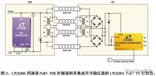
Linear Technology's LTC4266 (see Figure 2) is the first four-channel PSE controller on the market that fully complies with the 802.3at standard and is backward compatible with the popular 802.3af device LTC4259A. The LTC4266 not only provides PD with the power levels mandated by the new standard, but is also backward compatible with the original PoE standard, thus allowing users to mix and match up to 4 PoE and PoE + PD. As mentioned earlier, in order to comply with the 802.3at standard, a PSE must be able to provide 30W of power at the output of the PSE connector, so that after compensating for cable losses, it can deliver 25.5W of power to the PD. The LTC4266 can provide 30W of power, but it does this by greatly reducing heat dissipation.
When designing the next generation of PSE, you should choose a PSE controller that can provide a higher power level, implement a new classification mechanism, and provide a reliable PoE system that can efficiently deliver power. The LTC4266 has extremely low heat dissipation, so the thermal design of its application is significantly simplified compared to PSE controllers that integrate MOSFETs that are not very robust and usually have high RDS (ON) MOSFETs. The LTC4266 supports external MOSFETs, and if a port fails due to MOSFET failure, this failure will not produce a "domino" effect and cause adjacent channels to be implicated. This happens to be a concern when using internal MOSFETs. The accuracy of the LTC4266 allows the use of low-value detection resistors. More importantly, low RDS (ON) MOSFETs can also be used when managing line current and voltage. Because the resistance can be as low as 0.25Ω (for the sense resistor) and 0.09Ω (for the MOSFET), its maximum total channel resistance is only half that of other PSE controllers. In this way, the heat dissipation is significantly reduced, allowing designers to easily and reliably use the LTC4266 without a heat sink.
Power supply equipment that uses Linear Technology's four-channel PSE controller that fully complies with the IEEE802.3at standard has been put into use. Mid-span and end-span devices that can provide 30W of power on each port are currently available from stock. For PSE designers who are reluctant to design from scratch, the new PoETec PSE ICM (Integrated Connector Module) provided by many suppliers (including Molex, Tyco and Belfuse) is an ideal 8 Port and 12-port alternative solutions (using the LTC4266PSE controller).
PoE + PD design
The transition from 802.3af to 802.3at on the PD side will be slightly simpler, or at least the designer will need to consider fewer components to change, because only bridge rectifier components, PD controllers, and DC / DC control may be required The power requirements of this PD load can basically be met by the converter and transformer. Compared to PSE, heat dissipation is not a big problem in PD, but power efficiency still needs to be prioritized. The designer must also decide whether a PD will be able to support the auxiliary power from the wall adapter, or whether the PD load needs to be isolated. Similar to the PSE upgrade to PoE +, the success of the PD design depends largely on the PoE + PD controller.
To maximize the efficiency of PD, certain key decisions must be made. For isolated designs, it is best to avoid using optocouplers commonly used in converter feedback loops. However, perhaps the most important decision is to choose a flexible PD controller that can implement these high-efficiency methods. As a benchmark, Linear Technology ’s LTC4269 provides an unforgettable 94% efficiency level for isolated designs.
The LTC4269 is a PD controller that fully complies with the IEEE802.3at standard and is a companion device for the LTC4266 (see Figure 2). The LTC4269 is a full-featured PD controller with an integrated switching regulator and has an auxiliary power supply support capability as low as 16V. Although the 802.3at standard sets the upper limit of PD power to 25.5W, the LTC4269 does not set a current limit and can easily provide more than 30W of power, thereby creating a proprietary power stage and achieving PoE + The PD function outside the scope of the standard opens the way. The reliability of the LTC4269 is enhanced by integrating a robust 100V Hot Swap MOSFET. The MOSFET is responsible for isolating the PD controller and DC / DC converter during detection and classification, and providing a 100mA inrush current to achieve a smooth power-up conversion with any PSE.
To optimize the PD design, LTC4269 provides two versions. The difference between these two versions is the special switching power supply used. LTC4269-1 integrates a synchronous flyback controller, while LTC4269-2 integrates a synchronous forward controller. The flyback converter provides a low component count design, which has the advantage that additional output can be obtained by simply adding windings, while the forward controller can provide slightly better performance than the flyback at higher load currents. The efficiency of the excitation controller. In both cases, synchronous rectification provides higher output power, improved conversion efficiency, and improved cross-regulation performance (in applications with multiple outputs). In addition, in low-noise system design, the controller can also be synchronized to an external oscillator.
It is also worth noting that LTC4269-1 uses Linear Technology ’s patented No-Opto (no optical isolator) feedback topology to provide a complete IEEE802.3 without the need for additional optical isolator circuits. Isolation (see Figure 3). This eliminates the disadvantages of implementing optocoupler feedback, including variable loop gain due to optocoupler tolerances, high temperature sensitivity, and higher cost. The traditional optocoupler and shunt regulator used in the feedback loop have been replaced by an additional winding on the existing transformer to improve the regulation performance and efficiency and simplify the circuit.

Summary of this article
The PoE + standard brings higher power and better classification methods to the established PoE network industry. To comply with the PoE + standard, a PSE must provide 30W of power for the data or spare pair, and the power drawn by a PD at the input of the RJ45 connector must not exceed 25.5W. A PSE that complies with the PoE + standard must be able to perform single-event hardware classification, while the new two-event classification and LLDP data layer classification are optional high-power classification mechanisms. On the powered device side, the PD must be able to respond to the two-event classification (by the PD controller) and LLDP (by the PD microprocessor). PoE + compatible design has been put into use.
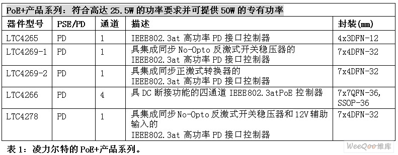
Linear Technology's LTC4266 and LTC4269 are the first new PoE + designs available on the market. Their introduction enables PSE and PD manufacturers to produce next-generation devices. Linear Technology is actively involved in the work of the IEEE802.3at task force and is developing more products that comply with the IEEE802.3at standard. Table 1 completely lists the PoE + devices released by Linear Technology. These new products will provide Linear Technology's existing PD products with a pin-compatible upgrade path, designed to achieve a smooth transition to the new PoE + standard. Linear Technology's products will continue to provide rugged design and field-proven reliability, and are strongly supported by rich technical experience, which is accumulated through years of designing PoE products for many applications.
We are into offering high performing range of Solar Home Systems, which is developed to provide power for daytime loads. These systems are highly demanded at rural as well as urban areas. Our Solar Home Systems are integrated with latest technology that ensures superior performance. We are counted as one of the leading Manufacturers, Suppliers and Exporter of Solar, Home Systems. The direct output of solar energy is generally 12VDC, 24VDC, 48VDC. To provide electricity to the 220VAC appliances, the direct current generated by the home solar power generation can be converted to AC power, so the dc-ac inverter is required.
3Kw Solar Home Power,Home Power,Solar Home Power
Yangzhou Bright Solar Solutions Co., Ltd. , https://www.cnbrightsolar.com