
Since the IF filter is behind a low noise amplifier, the insertion loss of the IF filter can be ignored as long as the low noise amplifier provides sufficient gain and does not introduce excessive signal distortion.
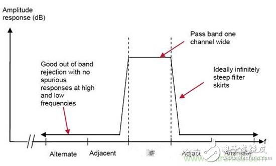
The main receiver indicator embodied by the IF filter is the adjacent channel rejection capability, and the IF filter can obtain typical adjacent channel suppression capability ranging from 30dB to 90dB. The center frequency used in the 12.5k PMR system is 21.4M, and the channel 7.5kHz crystal filter has an out-of-band rejection of 90dB (8.75k from the center point).
The IF filter must take into account the frequency deviation (caused by the receiver and transmitter crystal mismatch or temperature changes), so the IF filter bandwidth is usually larger than the signal bandwidth, which will cause the adjacent channel rejection to decrease. The suppression capability for the altenate channel and the farther channel is mainly determined by the IF filter transition band falling speed and the final stop band rejection capability.
Image suppression filter (Image filter)
For the sake of discussion, here we specify that the local oscillator frequency is less than the RF frequency. The reason why the image signal is suppressed is because the image signal is downconverted and the desired signal falls within the same bandwidth.
The rejection of the image signal is usually determined by the input bandpass filter and the image rejection filter. Since both filters operate at the RF frequency, high Q values ​​are required. High Q filters are expensive and difficult to implement, so the bandwidth of the input bandpass filter and the image rejection filter is usually relatively high. Reduce the Q value.
At the same time, it should be noted that the input bandpass filter is at the receiver input. Therefore, this filter is the main contributor to the receiver noise figure (NOISE FIGURE). In order to reduce the total noise figure of the receiver and improve the sensitivity, the input bandpass is required. The filter has a relatively small insertion loss.
Since the image rejection filter is behind a low noise amplifier, its insertion loss contributes less to the receiver's overall noise figure (NOISE FIGURE), but only if the LNA has sufficient gain and linearity to amplify the input signal without causing distortion.
In a superheterodyne receiver structure, usually the intermediate frequency (IF) frequency is fixed. Since the receiver needs to receive signals of multiple channels in one frequency band, the image rejection filter is required to provide sufficient image rejection capability for multiple channels. .
Image signal rejection is typically required to range from 40dB (DAB) to 70dB (PMR system). In order to provide sufficient image rejection for multiple channels, one approach is to utilize a fixed image rejection filter that is wide enough to cover the entire frequency band. as the picture shows:
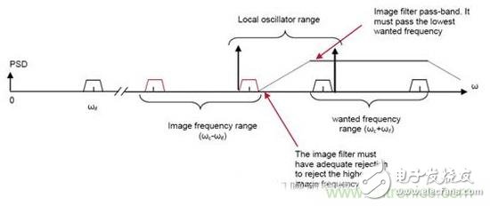
The image rejection filter covers the entire frequency band and down-converts the required channel to a fixed intermediate frequency by adjusting the local oscillator frequency. The design of the image filter needs to satisfy two conditions (here, the local oscillator frequency is assumed to be less than the RF frequency)
(1) The bandwidth of the image filter can cover the entire frequency band
(2) The image signal of the highest frequency channel is outside the image filter band
For example, for system parameters: channel spacing 2M, center frequency 340M, channel number 5, respectively at frequency points 336M, 338M, 340M, 342M, 344M, intermediate frequency frequency 36.13M.
For component 1, the image filter bandwidth is at least 10M, and the cutoff frequency at both ends is 345M, 335M.
For condition 2, the highest frequency channel image frequency is at 271.74M "335M"
In fact, for the conditions (1), (2), under the theoretical conditions, can we design a fixed image filter, it can be seen that the bandwidth of the entire frequency band can be less than twice the IF bandwidth.
If you need to use a fixed suppression image filter, you need to increase the IF frequency. Excessive IF frequencies result in difficult design of narrowband channel selection filters operating at intermediate frequencies.
Usual solution
A wideband IF filter is used, and the high IF signal is downconverted to a low IF frequency by means of secondary mixing. To use this method, care must be taken to ensure the linearity of all receiver modules before the channel filter, and to filter out twice. An image signal formed before mixing.
Valve Mechanism,Valve Operating Mechanism,Overhead Valve Mechanism,Side Valve Mechanism
Chongqing LDJM Engine Parts Center , https://www.ckcummins.com