
The Hardware Connection MPSoC can receive two sets of interrupt signals from the PL. In Vivado, you can enable this by navigating to PS-PL Configuration → General → Interrupts → PL to PS → IRQ0/IRQ1.
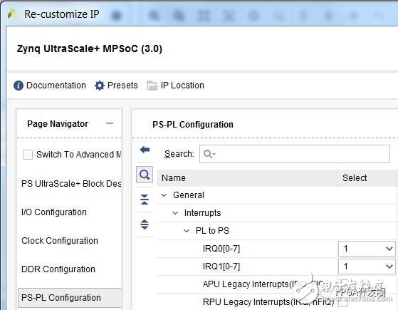
The corresponding hardware interrupt numbers are as follows: PL PS Group 0: 121–128 PL PS Group 1: 136–143
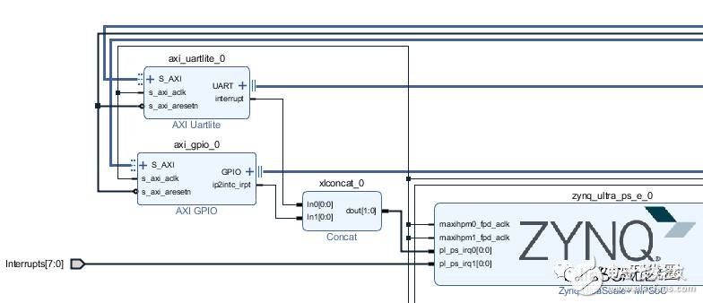
These two interrupt signals can be connected either to an IP's interrupt pin in IPI or to logic written in Verilog. If multiple interrupt sources need to be combined into one signal group, you can use the concat function to merge them before connecting to the IRQ.
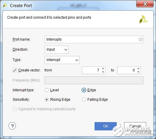
If you want to introduce an interrupt signal from Verilog, right-click in the IPI and select "Create Port." Set the port type to "Interrupt."
Hardware and Software Bridge: Device Tree
How does the hardware information get passed to the software system? The answer for Linux is the Device Tree.
The following is the device tree automatically generated by the Device Tree Generator for AXI UARTLite in the figure above:
Axi_uartlite_0: serial@a0000000 {
clocks = <&misc_clk_0>;
compatible = "xlnx,xps-uartlite-1.00.a";
current-speed = <115200>;
device_type = "serial";
interrupt-parent = <&gic>;
interrupts = <0 89 1>;
port-number = <1>;
reg = <0x0 0xa0000000 0x0 0x10000>;
xlnx,baudrate = <0x2580>;
xlnx,data-bits = <0x8>;
xlnx,odd-parity = <0x0>;
xlnx,s-axi-aclk-freq-hz-d = "99.999";
xlnx,use-parity = <0x0>;
};
Create Device Tree A device tree is a plain text file with a .dts or .dtsi extension. While it's possible to write it manually, Xilinx provides tools to help automate the process. One common method is using PetaLinux, which generates the device tree during the petalinux-build process. When importing an HDF file into a PetaLinux project, the build process triggers the Device Tree Generator (DTG) to create the device tree. You can then modify the generated file, but keep in mind that it may be overwritten during future builds.
Another way to generate a device tree is through the SDK. The SDK can load the DTG as part of the BSP generation. You can download the DTG from [https://github.com/Xilinx/device-tree-xlnx](https://github.com/Xilinx/device-tree-xlnx). Once downloaded, extract the folder and add it to the SDK’s Xilinx Tools → Repositories. Then, create a new BSP in the SDK and choose the device_tree option for the BSP type.
Note: For SDx users, the process is similar—go to Window → Preferences → Xilinx SDK → Repositories.
Interrupt Properties in Device Tree The interrupt definition in the device tree includes two key properties: interrupts and interrupt-parent. The interrupt-parent points to the interrupt controller. MPSoC has several peripherals with interrupt controller capabilities, such as GIC, GPIO, and PCIe.
The parameters in the interrupts property define the interrupt number and its attributes. These definitions are detailed in the interrupts.txt file under the device tree bindings. It’s important to note that the #interrupt-cells property in the interrupt controller specifies how many 32-bit values are needed for the interrupts parameter. Commonly, this ranges from 1 to 3 cells.
For example, with one cell, only the interrupt number is provided. With two cells, the number and trigger type are included, as seen in the GPIO controller. The ARM GIC uses three cells:
First cell: Indicates the interrupt type. 0 for SPI (Shared Peripheral Interrupt), 1 for PPI (Private Peripheral Interrupt). Since the PL to PS interrupt is an SPI, we use 0. Second cell: Contains the interrupt number. Third cell: Specifies the interrupt trigger mode (edge or level).
According to the arm,gic-v3.txt documentation:
First cell: 0 for SPI, 1 for PPI. Other values are reserved. Second cell: SPI numbers range from 0–987; PPI numbers from 0–15. Third cell: Bits [3:0] define the trigger type. 1 = edge triggered, 4 = level triggered.
Determine the Interrupt Number When defining the interrupt number in the device tree, subtract 32 from the hardware interrupt number. This is because the kernel maps the hardware interrupt number to a virtual one.
Writing an Interrupt Driver
PetaLinux comes with an example of an interrupt service routine. You can create a sample module using the command: petalinux-create -t modules -n mymodule.
The code snippet for registering the IRQ is as follows:
/* Get IRQ for the device */
r_irq = platform_get_resource(pdev, IORESOURCE_IRQ, 0);
if (!r_irq) {
    dev_info(dev, "no IRQ found");
    dev_info(dev, "mymodule at 0x%08x mapped to 0x%08x",
             (unsigned int __force) lp->mem_start,
             (unsigned int __force) lp->base_addr);
    return 0;
}
lp->irq = r_irq->start;
rc = request_irq(lp->irq, &mymodule_irq, 0, DRIVER_NAME, lp);
if (rc) {
    dev_err(dev, "testmodule: Could not allocate interrupt %d.", lp->irq);
    goto error3;
}
Keep in mind that this code retrieves the interrupt number from the device tree and assigns a virtual number to the OS. Previously, developers had to hardcode the interrupt number in C, but this approach is no longer recommended. Instead, always use the virtual interrupt number obtained from the device tree.
Power transformer Station:
. Step-up transformer
. Step-down transformer
. Oil immersed transformer
. Dry type transformer
. Containerized transformer
. Transformer substation
. Packaged power substation
Power Trandformers,Distribution Transformer,Transformer Substation,Oil Immersed Tramsformer
Guangdong Superwatt Power Equipment Co., Ltd , https://www.swtgenset.com