
RF (Radio Frequency) technology is widely used in many fields, such as: television, radio, mobile phones, radar, automatic identification systems.
The special word RFID (Radio Frequency Identification) refers to the application of radio frequency identification signals to identify the target.
RFID applications include:
ETC (Electronic Charge)
Railway Locomotive Vehicle Identification and Tracking
Container identification
Identification, certification and tracking of valuables
Target management for commercial retail, healthcare, logistics services, etc.
Entry control
Animal identification, tracking
Vehicle auto lock (anti-theft)
RF (Radio Frequency) refers to electromagnetic waves that have a certain wavelength that can be used for radio communication. Electromagnetic waves can be expressed by their frequencies: KHz (kilohertz), MHz (MHz) and GHz (gigahertz). The frequency range is VLF (very low frequency), that is, 10-30 KHz to EHF (very high frequency), that is, 30-300 GHz.
RFID is a flexible application technology that is easy to handle, simple and practical, and especially suitable for automated control. Its unique superiority is beyond the reach of other identification technologies. It supports both read-only mode and read-write mode, and requires no contact or aiming; it can work freely in a variety of harsh environments; it can be highly integrated. In addition, because the technology is difficult to be counterfeited and invaded, RFID has a very high security protection capability.
Conceptually, RFID is similar to bar code scanning. For bar code technology, it attaches the encoded bar code to the target and uses a dedicated scanning reader to transmit information from strip magnet to scan read and write using optical signals. RFID uses a dedicated RFID reader and a dedicated RFID unit that can be attached to the target to transmit information from the RFID unit to the RFID reader using RF signals.
The RFID unit carries various types of related information about the target object, such as the name of the target object, the start and end point of the target transportation, the transit point, and the specific time when the target object passes through a certain place, etc., and can also load such as temperature. And other indicators. RFID units, such as labels, cards, etc., can be flexibly attached to various items from the vehicle to the cargo chassis.
The frequency of radio waves used in RFID technology is 50KHz-5.8GHz. As shown in Figure 1, a basic RFID system generally includes the following parts:
An RFID unit (answering machine or card, label, etc.) carrying information about the target
Antenna for transmitting RF signals between readers and RFID units
An RF transceiver that generates RF signals
A reader/writer that receives the RF signal returned from the RFID unit and transmits the decoded data to the host system for processing.
The antenna, reader, transceiver, and host can be partially or fully integrated into a single unit or integrated into a small number of components. Different manufacturers have different integration methods.
(In addition to the above basic configuration, the corresponding application software should also be included)
RF technology - typical RF circuitThe most important application area of ​​RF circuits is wireless communication. Figure 1 is a block diagram of a typical wireless communication system. The following uses this system as an example to analyze the role of RF circuits in the entire wireless communication system.
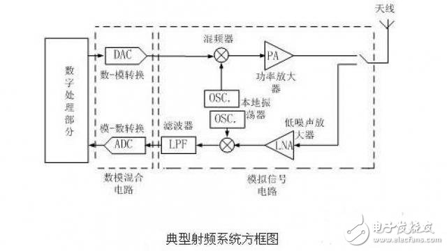
This is a system model of a wireless communication transceiver ("span" tranceiver) that includes a transmitter circuit, a receiver circuit, and a communication antenna. This transceiver can be used in personal communications and wireless local area networks. In this system, the digital processing part mainly processes the digital signal, including sampling, compression, encoding, etc.; then it becomes an analog form into the analog signal circuit unit through the A/D converter.
RF technology - the composition and characteristics of the circuitIn the following, the composition and characteristics of a general RF circuit will be discussed with respect to a low noise amplifier (LNA) in the block diagram of the figure.
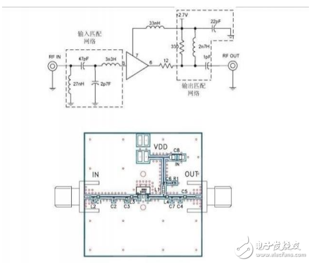
The board above shows the board diagram of this amplifier, noting that the input signal is passed through a matched filter network input amplification module. The amplification module generally uses a common emitter structure of the transistor, and its input impedance must match the output impedance of the filter located in front of the low noise amplifier to ensure optimal transmission power and minimum reflection coefficient. For RF circuit design, this Matching is a must. In addition, the output impedance of the low noise amplifier must match the mixer input impedance at the back end, as well as ensuring that the amplifier output signal is fully and non-reflective input to the mixer.
These matching networks are composed of microstrip lines and sometimes may be composed of independent passive components, but their electrical characteristics at high frequencies are quite different from those at low frequencies. It can also be seen that the microstrip line is actually a copper strip of a certain length and width, and the microstrip line is connected with a chip resistor, a capacitor and an inductor.
RF Technology - Power and Gain of CircuitsGain, noise, and nonlinearity are the most commonly used indicators for describing RF circuits. In RF and microwave systems, the measurement of voltage and current parameters commonly used in low frequency circuits becomes very difficult due to the ubiquity of reflection and the ideal short circuit and open circuit. Therefore, power measurement has been widely used.
Moreover, conventional RF and microwave circuits are constructed using discrete components and transmission lines. The input and output of the circuit typically need to be matched to a system impedance (50 Ω or 75 Ω). For the above two reasons, the performance indicators of the circuit, such as gain, noise, nonlinearity, etc., can be expressed by power.
For the convenience of calculation, power is used in the form of logarithm of power intensity in RF and microwave engineering, and dBm is the logarithm of signal power with respect to 1 mW.
With the definition of power, it is now time to discuss an important indicator in the RF system: gain. The power considered in the RF system refers to the power gain, which is easily confused with the voltage gain. In addition, in the RF system, there are also multiple power definitions. When the matching circuit is present, the following power can be defined:
PL: power obtained by the load
Pin: input power of the circuit
Pavs: the maximum power that the source can provide
Pavn: the maximum power that the circuit can provide
Accordingly, three types of power can be defined: a general power gain Gp, a converted power gain GT, and a capital gain GA.
Mini Circuit breakers, also named as the air switch which have a short for arc extinguishing device. It is a switch role, and also is a automatic protection of low-voltage electrical distribution. Its role is equivalent to the combination of switch. Fuse. Thermal Relay and other electrical components. It mainly used for short circuit and overload protection. Generally, According to the poles, mini Circuit breaker can be divided into 1P , 1P+N , 2P, 3P and 4P.
Miniature Circuit Breaker,Electronics Miniature Circuits Breaker,Automatic Miniature Circuit Breaker,Mini Circuit Breaker,MCB
Wenzhou Korlen Electric Appliances Co., Ltd. , https://www.zjmoldedcasecircuitbreaker.com