Differential current drive differential LED energy saving lamp
Output adjustable charging, such as Catalyst's CAT3200-5, is one of the ambitions of LED energy-saving lamp drivers that can deliver up to 100mA of load current while achieving a 5V regulated output. The current of a white LED energy-saving lamp for LCD backlight is usually 20 mA, and the forward voltage VF is about 3.4V. The current on each LED energy-saving lamp is set by a series resistor, also known as a ballast resistor (see Figure 1). This configuration allows differential currents to be passed in parallel on the LED energy saving lamp. A larger resistance value means a smaller current on the LED energy saving lamp. Equation 1 can be used to approximate the current on the LED energy-saving lamp (ignoring interconnection consumption).
Formula 1: VOUT=VF+ (LED energy saving lamp current × RS)
Among them, VF is the forward voltage of the LED energy-saving lamp, and RS is the series resistance.
The output voltage VOUT is stable at 5V. Considering that when the forward voltage VF is 3.4V, the current on the LED energy-saving lamp is 20mA, then RS=(5V-3.4V)/20mA, that is, 80 ohms. In this example, three white LED energy-saving lamps were received as backlights for the screen, and two color LED energy-saving lamps (red and blue, respectively) were used as indicators. Each color LED energy saving lamp has a differential forward voltage characteristic. The forward voltage of the red LED energy-saving lamp is very low, and the voltage is usually 2.8V when passing 20mA. Since the indicator LED energy-saving lamp does not consume illumination, its current is smaller than the backlight LED energy-saving lamp.
The CAT3200-5 charge is a voltage doubler that requires only one large capacitor to act as a reservoir to transfer charge from the input to the output. Here we recommend using a 1μF ceramic capacitor. All the external components required are the other two 1μF capacitors placed on the input and output pins.
There are other LED energy-saving lamp price driver implementations on the market, such as inductor boost or current controlled charging. The inductive boost driver accepts an inductor that boosts the input voltage to drive several LED energy-saving lamps in series. It has the advantage of providing the same current on these LED energy-saving lamps, but this configuration should not be used in the above application examples. Another type of LED energy-saving lamp driver is current-controlled charging. By using an on-chip current regulator, a separate LED energy-saving lamp channel can drive an LED energy-saving lamp. In this case, the size of the current on the LED energy-saving lamp is set by an external resistor. In a larger drive, it can be programmed into the chip via a digital interface. The benefit of this structure is that ballast resistance is no longer necessary. Since the currents on all LED energy-saving lamps are the same, this management solution should not be used as the application we discussed.
Inrush current
The most critical headings often come when the system is powered up. When the signal of the "enable" input pin transitions from logic low to logic high, the device turns on and begins charging the bulk capacitor. As a result, the input current sharply increases in a short time, resulting in a so-called "surge" current. One indicator of the advantages of the form factor power management chip is how it is reflected in monitoring the input current. The risk of high surge currents is that the internal rail voltage (VRAIL) momentarily falls and affects system operation. The drop in rail voltage is a function of the power supply output impedance RS and the interconnect impedance RINTER.
The calculation formula of the system rail voltage is: VRAIL=VBAT-IIN×(RSINTER,
Here, VBAT is the battery voltage and IIN is the input current. For example, if the sum of the series resistances is 1.5 (the surge current is 0.5 A, the rail voltage is: VRAIL = 3.6 V - (0.5 A x 1.5 ohms) = 2.85 V.
A low voltage can cause the system to collapse. One way to eliminate the battery output surge current is to increase the input capacitance CIN. As a result, most of the current that charges the large capacitor is supplied by the capacitor CIN, which eliminates the inrush current.
The input current waveform reflects an increase in input current as the output voltage increases linearly to a nominal 5V. The initial current spurs have little effect on the input voltage because there is only a short 2μs continuous time, so there is no harm.
Adjustable charging provides a good management solution for driving LED energy-saving lamps and is easy to implement on PCB boards. When selecting such a device, some of the key parameters that must be considered include the output current size, input voltage range, power-on sequence, switching frequency, and low-noise event performance.
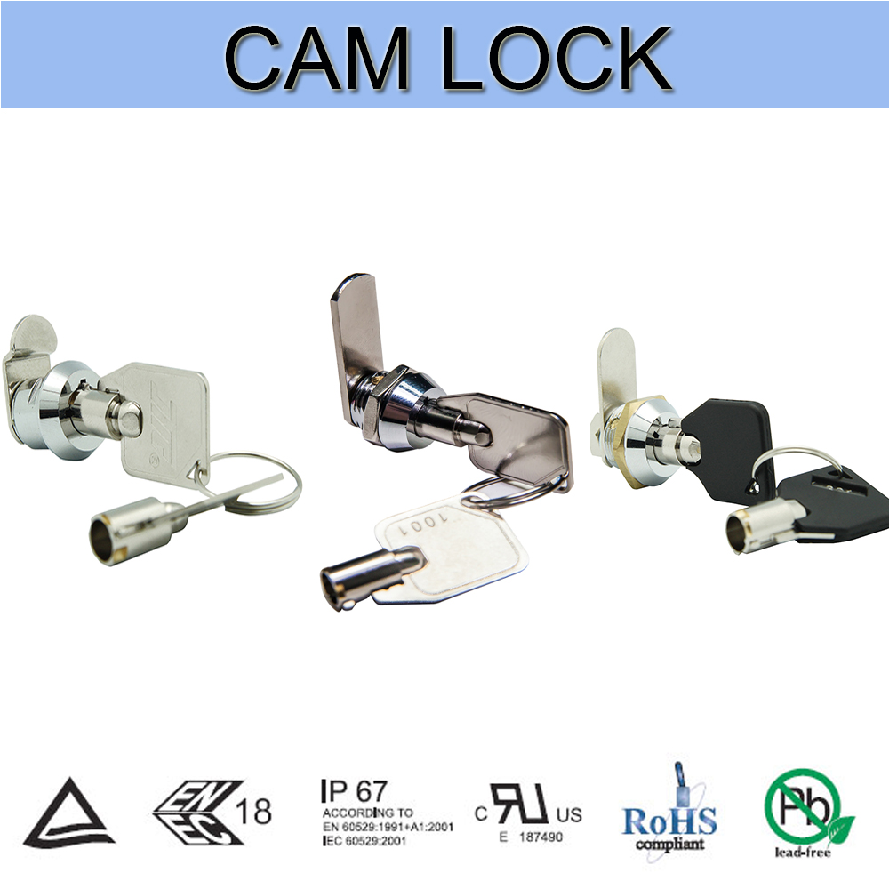
Cam lock, as the name implies, is Mechanical key lock. Our mechanical lock series products are divided into 12mm, 16mm and 19mm according to size also could be divided into Cabinet CAM Lock with keys and Drawer CAM Locks without keys
This cam lock cover a wide range of applications and can be used in large entertainment equipment, like ,vending machines, mechanical equipment, lockers, etc.

We have introduces high-precision CNC numerical control milling machine and multiple automatic processing equipment at home and abroad to improve cam lock` s precision,insuring all the cam lock cant be replaceable or copy. The specification is as follows:
Zinc alloy die cast housing and cylinder
Barrel chrome plated standard
Tumbler mechanism is pin or disc
It could be zinc alloy tubular Key Switches or flat key switch or without keys enter
Key may be withdraws in one or both positions
Hex nut or speed clip mounted
Have Multiple combination function.
CAM Lock
CAM Lock,Cabinet CAM Lock,Safe CAM Lock,Drawer CAM Locks
YESWITCH ELECTRONICS CO., LTD. , https://www.yeswitches.com
