
Bluetooth technology is an open specification for wireless data and digital communications. Based on low-cost, close-range wireless connectivity, it establishes a complete communication method and technology for fixed and mobile devices. The essence of Bluetooth technology is to establish a standard for universal wireless interfaces and their control software, so that mobile communication and computer networks can be seamlessly connected, thereby providing close range (10m~100m) range for portable devices produced by different manufacturers. Interoperable channel within.
In industrial control systems and many applications, with the development of electronic technology, controllers and sensors have been intelligent. In general sensors or test instruments, digital control technology under CPU control is used extensively, and thus many control systems or sensor systems have been digitally transmitted. If Bluetooth technology is embedded in digital control systems and sensors, wireless transmission of system data and control commands can be achieved, which is important for many applications.
This paper proposes an embedded SoC device structure through the discussion of the structure of the Bluetooth protocol stack. This embedded SoC device is a SoC device with Bluetooth communication function; the CPU in the SoC is open to the user, and the user can implement the smart sensor or controller unit using the SoC device of this structure.
1 Bluetooth protocol stack
The Bluetooth Technical Specification version 1.0 is as follows.
Bluetooth works in the worldwide-free 2.4GHz ISM (Industrial, ScienTIfic and Medical) free, application-free radio band.
Fast acknowledgment and frequency hopping techniques are used to ensure link stability.
A frequency hopping transceiver with binary frequency modulation (FM) technology that suppresses interference and prevents fading.
Forward error correction (FEC) technology is used to suppress random noise on long-distance links.
The data transfer rate is 1Mb/s.
With time division duplex transmission, the baseband protocol is a combination of circuit switching and packet switching.
One hopping frequency transmits one synchronization packet, each packet occupies one time slot, and can also be extended to five time slots.
Supports an asynchronous data channel, or 3 concurrent synchronous voice channels, or a channel that simultaneously transmits asynchronous data and synchronized voice. Each voice channel supports 64Kbps of simultaneous voice. The asynchronous channel supports an asymmetric connection with a maximum rate of 721 Kbps, a reverse response rate of 57.6 Kbps, or a symmetric connection of 432.6 bps.
Currently, in the wireless LAN technology working in the 2.4 GHz band, in addition to Bluetooth technology, there are IEEE802.11, HomeRF and infrared technologies. In general, IEEE802.11 is more suitable for office wireless networks, HomeRF is suitable for communication between mobile data and voice devices in the home, and Bluetooth technology can be applied to any occasion that allows wireless to replace cables. .
In practical applications, the application of Bluetooth technology generally uses embedded technology. Embedding the Bluetooth protocol stack in the application system provides a transparent wireless network communication layer for the system.
The design of the Bluetooth technology protocol stack can only achieve the seamless connection of products from different manufacturers if it meets the requirements of the Bluetooth technical specifications. The Bluetooth specification (specificaTIon) includes two parts, a protocol and an application profile. The complete Bluetooth protocol stack is shown in Figure 1.
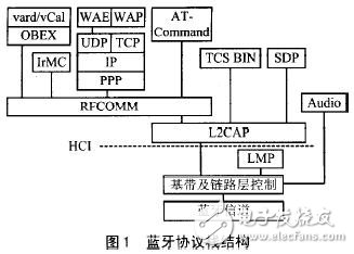
The protocol specification defines the working mode of each functional element, and provides a horizontal architecture between functional elements in the implementation of Bluetooth technology. The application specification describes the implementation of a specific application model, describes the synergy mechanism between the layers of the protocol, thus providing a vertical architecture of the technology implementation. The Bluetooth protocol includes a core protocol layer, an alternate cable protocol layer, a telephony control protocol layer, and an optional protocol layer.
Core agreement. Core protocols include baseband protocols, Link Management Protocol (LMP), Logical Link Control and Adaptation Protocol (L2CAP), and Service Discovery Protocol (SDP).
Alternative cable protocol. The alternative cable protocol includes the Serial Circuit Emulation Protocol (RFCOMM) for data conversion.
Telephone replacement agreement. This Agreement includes the TCS Binary and the AT-command. A processing specification and corresponding control commands for providing audio communication.
Optional agreement. The selection protocol is related to the user's application, including point-to-point protocol (PPP), user datagram/transmission control protocol/internet protocol (UDP and TCP/IP), target exchange protocol (OBEX), wireless application protocol (WAP), wireless Application Environment (WAE), vCard, vCal, Infrared Mobile Communications (IrMC). The specific content of the selection protocol layer is selected by the application system as needed.
In addition to the above protocol layers, the Bluetooth protocol stack should also include two interfaces: one is the Host Control Interface (HCI), which provides a command interface for the baseband controller, link controller, and access hardware status and control registers. The other is an audio interface directly connected to the baseband processing section for transmitting audio data.
In the Bluetooth protocol stack, the above part of the HCI is usually implemented in software, including the logical link control and adaptation protocol L2CAP, serial emulation RFCOMM, link management protocol (LMP), telephone replacement protocol and optional protocol; while the following part of HCI Implemented in hardware, including the baseband protocol and Link Management Protocol (LMP), which is also referred to as the underlying hardware module in the Bluetooth protocol architecture.
2 Bluetooth core protocol stack hardware circuit structure
The underlying module is the core module of the Bluetooth technology, and is mainly composed of a radio frequency (RF) unit circuit, a base band circuit, and a Link Manger Protocol (LMP) circuit.
(1) Radio frequency (RF) unit
The RF unit circuit provides the physical layer of communication for Bluetooth technology, also known as the Bluetooth transceiver. The data stream is filtered and transmitted through a 2.4 GHz microwave. The Bluetooth protocol provides technical specifications for Bluetooth transceivers.
(2) baseband layer circuit
The baseband layer provides baseband digital signal processing hardware whose function is to provide link control and is therefore also referred to as baseband and link control layer circuitry. Through the baseband layer circuit, physical links in the Bluetooth communication network can be established to form a piconet. There are two physical links in the baseband layer, one is a connection-oriented synchronous link (SCO) and the other is an asynchronous connectionless link (ACL). In addition, the baseband layer can provide different levels of Forward Error Correction (FEC) or Cyclic Redundancy Check (CRC) processing for voice and data packets and can encrypt data. At the same time, the baseband layer circuitry provides specific channels for different types of data, including transport information data, link management, and control information.
(3) Link management layer (LMP) circuit
The link management layer circuit, also known as the link manager circuit, functions to provide a link management communication protocol. The link management protocol is used to set and control the link, and is responsible for establishing and revoking the connection, power control, authentication and encryption between the Bluetooth devices, and also controlling the working state of the Bluetooth device (holding hold, sleeping park, breathing sniff) And activities acTIve). The main function of the link management layer is done by software, and the link manager circuit provides software running in the processor of the Bluetooth device. The communication protocol between link managers is called Link Management Protocol (LMP).
The overall framework of the Bluetooth technology is defined by the HCI (Host Controller Interface) and is divided into two parts: the hardware module and the upper layer software protocol. In the Bluetooth technology standard, USB, UART or RS232 is selected as the interface between the hardware module and the host. When the Bluetooth module is connected to the host by any one of USB, UART or RS232, the communication protocol of the upper layer of the HCI interface is handled by the host, and the communication protocol of the lower layer of the HCI interface is responsible for the baseband layer chip and the RF chip within the module. According to the Bluetooth standard, the basic components of a Bluetooth system include an antenna, a transceiver, and a baseband controller. It can be seen that with the support of the antenna, the RF receiver and the baseband controller, the composition of the Bluetooth system can be very flexible, and a variety of different implementation schemes can be realized.
The embedded Bluetooth system integrates the RF and baseband components on a single chip. The structure of the single-chip Bluetooth hardware module is shown in Figure 2. In the embedded Bluetooth device, the hardware structure can be divided into link manager, link controller and RF module 3, which is responsible for processing the LMP layer, baseband layer and RF layer protocol. The link manager contains components such as a processor (CPU) and memory. The link manager and the baseband layer chip are collectively referred to as a link controller. The RF module contains an RF RF transmitter component, and the interface to the host is located on the link controller.
In the embedded solution, the upper layer software protocol of the Bluetooth protocol is also solidified in the chip, and the chip is connected to the application system through a USB or UART interface. Since the CPU is embedded in the chip, the embedded Bluetooth system is actually a smart terminal suitable for any system with a CPU device. For example, in a smart sensor, by adding a single-chip Bluetooth device, a Bluetooth-based sensor can be formed.
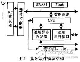
As shown in Figure 2, it consists of a microprocessor (CPU), a wireless transceiver (RF), a baseband controller (BB), a flash memory (Flash program memory), a universal asynchronous transceiver UART (Universal Asynchronous Receiver Transmitter), and a universal serial. Interface USB (Universal Serial Bus) and Bluetooth test module. The Bluetooth baseband controller is a key module of the Bluetooth hardware module. Its main function is to realize all real-time processing functions of the Bluetooth baseband part under the control of the microprocessor, including responsible for symbol timing extraction and recovery of the received bit stream; cyclic redundancy check (CRC) of the packet header and payload. , packet header and payload forward error correction code FEC processing, encryption and decryption processing, etc., and can provide interfaces from the baseband controller to other chips. The CPU generally adopts an embedded microprocessor of RISC structure, such as the ARM7TDMI microprocessor, in order to satisfy the high-speed processing of the Bluetooth core protocol and the processing of a large amount of data bit stream. Flash memory is used to store all protocol software in the baseband and link management layers. SRAM is used as the running space of the CPU, and the software in Flash is loaded into SRAM during work. The RF transceiver is responsible for receiving or transmitting high frequency communication signals. The UART and USB interfaces provide a physical connection to the HCI's host controller interface transport layer, which is the channel through which the upper layer protocol communicates with the Bluetooth hardware module. The Bluetooth test module mainly provides certification and conformance specifications for the wireless layer and the baseband layer, and also manages the production and after-sales testing of the product as an optional module.
Medical thermomter Features
1. The medical Infrared Thermometer is multi-purpose machine for body/room/milk/water
2. Use high accuracy rating Belgium infrared probe, accuracy is ±0.2℃
3. Thermometer with 32 sets memories, let you check history easily
4. 3 color for backlight dispaly with high temperature alarm: green, orange, red color
5. Thermometer is automatic turn off in 20 seconds
7. Passed EMC LVD test, FDA, CE registed products
Medical Clinical Infrared Thermometer
Infrared Thermometer Medical,Clinical Infrared Thermometer,medical infrared forehead thermometer
Axiswell Technology Co., Ltd , https://www.medhealthycare.com