
Keywords: low voltage control cabinet, monitoring system, MODBUS protocol
1 Introduction Fieldbus is a system that is applied at the production site and realizes bidirectional serial multi-node digital communication between microcomputerized measurement and control equipment. It is also known as the open, digital, and multi-point communication bottom control network.
At present, most of the low-voltage distribution systems used in power distribution rooms in China have not realized intelligent control, and managers cannot find problems in time and deal with emergencies. The development of intelligent controller with communication function and its application on circuit breakers, as well as the application of intelligent network instruments, make it possible to realize the intelligentization of low-voltage power distribution through fieldbus. The low-voltage power distribution monitoring system collects the electrical parameter information and circuit breaker status information of each power distribution cabinet in the power distribution room to realize remote control, telemetry, remote adjustment, and remote communication of each power distribution cabinet.
2 Introduction to MODBUS protocol MODBUS is a communication protocol designed for the PLC produced by MODICON. From a functional point of view, it can be considered as a field bus. The MODBUS protocol defines the format of the message domain and the common format of the content, so that the controller can recognize and use the message structure without considering the topology of the communication network. It describes the process of a controller accessing other devices. When using the MODBUS protocol to communicate, this protocol specifies that each controller needs to know its own device address, identify the messages sent by the address, how to respond to requests from other devices, and how Detect errors and record.
The controller communication adopts the master-slave technology, that is, only the master device can issue an inquiry, and the slave device responds to the message. The master device can communicate with the slave device separately, and the slave device returns a message. If the broadcast method (address is zero) is used for query, the slave device will not make any response.
There are two modes of MODBUS communication: ASCII and RTU mode. Only one mode can be selected in a MODBUS communication system, and it is not allowed to mix the two modes.
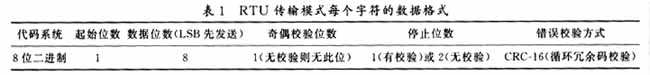
In RTU mode, the start bit of the message starts with a pause of at least 3.5 character transmission time (usually 4). After the last character is transmitted, there is a pause of at least 3.5 character transmission time to identify End. A new message can start after this pause. During the reception, if the time to wait for the reception of the next character exceeds 1.5 character transmission time, it is considered to be the start of the next message. The check code adopts CRCï¼16 mode, and only for the device address, function code and data segment. The entire message frame must be transmitted as a continuous stream, the transmission rate is higher than the ASCII mode.
The possible slave device addresses of MODBUS are 0 to 247 (decimal), and the address range of a single device is 1 to 247.
The possible function code range is 1 ~ 255 decimal. Some of these codes apply to all controllers, some are for a certain MODICON controller, and some are reserved or reserved for users.
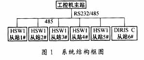
3 The system realizes the MODBUS standard physical layer adopts RS232 interface. Due to the strong electrical interference in the actual application and the multi-point connection, we use the RS485 interface. At the same time, due to the centralized installation of power distribution cabinets in the power distribution room, there is no need to adopt a complex network topology.
The upper computer adopts industrial control computer and connects with RS232 / 485 conversion interface. The circuit breakers are HSW1 series produced by a company, a total of 5 units. The main entry line adopts the French "SOCOMEC" company's "DIRISSYSTEM" intelligent power system power monitor. In order to ensure a faster transmission speed, the system communication adopts the RTU transmission mode recommended by MODBUS. Table 1 shows the data format of each character in the RTU transmission mode, and Table 2 shows the format of the MODBUS protocol RTU message frame. The communication medium connected to the system is A shielded twisted pair. The system block diagram is shown in Figure 1.

3.1 The main component of the low-voltage control cabinet of the intelligent controller is the HSW1 intelligent universal low-voltage circuit breaker. The block diagram of the circuit breaker hardware composition is shown in Figure 2.

Intelligent controller can set overload long delay inverse time limit, short delay inverse time limit, time limit, instantaneous function; can also collect setting current, action current, voltage of each line, and control the on / off of the circuit breaker; and through the built-in MAX485 chip realizes communication with the outside world.
When realizing the MODBUS protocol of the intelligent controller, the main difficulty lies in the realization of the pause time of the RTU mode. First, we calculate the time t required for each byte transmission. When USART is initialized, TImer1 of PIC18C658 is set to zero and timed. The time limit of TImer1 is 4t. The flow chart is shown in Figure 3. Because it is a continuous data stream in RTU mode, during the continuous reception of data, if the character reception time exceeds 2t, the current message is discarded. After receiving the information, use TImer1 timer interrupt to control the end time interval, and process data and errors at the same time.
3.2 Power monitor The DIRISC power monitor used in power grid monitoring can detect the phase voltage, line voltage, phase current, neutral current, active / reactive power, power factor, frequency and corresponding of the three-phase four-wire system. The maximum value. The monitor uses RS485 interface, adopts RTU mode in MODBUS protocol to connect with the outside world, and transmits power grid monitoring data. According to the actual application, the power monitor only uses some functions in the MODBUS communication protocol: 03 function, this function can read any measured value and set value parameters in the power monitor, and can read up to 128 words at a time; 06 function , This function can write set value parameters to the power monitor, this function can only write one word data at a time, 10 functions, this function can write multiple set value parameters to the power monitor, at most one can write more Setpoint parameters.
3.3 Realization of the upper computer software The upper computer software is developed by VC6.0, and the operating system is Windows NT4.0. The problem to be paid attention to in software programming is that, because the MODBUS protocol is developed by MODICON for its PLC, most commands are only applicable to the PLC of MODICON, so you need to add some commands yourself to meet the communication requirements. The main functions are as follows.
3.3.1 Remote control Remote control is the operation control of energy storage, closing and opening of each slave station circuit breaker through the master station industrial computer. The operator selects the corresponding object from the system interface, and the system provides the current operating state of the corresponding object, and can issue a remote control "close" or "minute" command. The system transmits the instruction to the corresponding circuit breaker slave station. After the slave station receives the instruction, it performs operations such as breaking, closing, and energy storage according to the predetermined timing, and reports the result of the remote control to the master station.
3.3.2 Remote adjustment Remote adjustment is to set the protection setting value of the slave station through the master station industrial computer. The protection setting tables of all slave stations are stored in the master station's industrial computer. After selecting an object, the system provides the current settings of all the protection setting values ​​of the corresponding object and the protection setting table of the object, which can be selected from the parameters The required parameters, and then click the corresponding button, the master station will download the parameters to the corresponding slave station, and report the results of remote adjustment. The slave station changes its own protection setting value after receiving the instruction.
3.3.3 Telemetry Telemetry is to monitor the grid operating parameters of each slave station through the master station. The communication sub-stations report the working parameters to the host computer as follows: the real-time A, B, C, and N-phase current values ​​of each sub-station, and the voltage values ​​of UAB, UAC, and UCA.
The fault record can record the following fault parameters: A, B, C, N phase current values ​​at the time of the fault, UAB, UBC, UCA voltage values, fault type, fault action time. And record these faults in the fault database.
The computer displays the current real-time current and voltage of each sub-station in a bar graph, absolute value table, etc., and displays the operating status of each node in a real-time curve.
3.3.4 Telecommunication

Telemetry is to check the model of the slave station, the closed and open status, the protection settings, and the operation and fault information status of the slave station through the master station computer. The main parameters of the breaker from the station to the host computer are: switch type, switch status (closed / open), fault information, alarm information, various protection settings, etc.
3.3.5 Other functions of the system In addition to the four remote operation control functions, the system also has a variety of management functions: accident alarm, event recording, maintenance and listing, handover management, load trend analysis, and various report printing.
4 Conclusion After one year of development and commissioning, the system is operating normally in the distribution room of Hangzhou Hongshen Electric Co., Ltd. After the system is put into operation, managers can monitor the system's operating status at any time, reducing labor intensity. At the same time, it provides real-time online analysis under fault conditions, which greatly shortens the time from fault alarm to troubleshooting, and realizes power distribution management The intended purpose of automation.
2 High-flying, etc. Simulate PLC on PC to realize MODBUS communication. Microcomputer Information, 2001 (5)
Universal Series Extension Sockets
Socket Extension,Trailing Socket,Plug Socket Extension,Single Socket Extension Lead
Heikki Technology Co., Ltd. , https://www.heikkipower.com