
The Design of Automobile Headlight Motion Control System Based on LIN Bus
introduction
With the development of society, automobiles are becoming more and more popular, automotive applications have become increasingly complex, and more and more electronic drives are used. Therefore, it is not surprising that more innovative technologies and special technologies are applied in this field. . With the increase of car ownership, the probability of traffic accidents also increases, especially when driving at night, the two cars meet, and the control of car headlights is an important issue. At present, cars often include those with dynamic position control. For headlamps, especially for high intensity discharge (HID) xenon lamps, dynamic position control is critical. However, the headlight positioning system imposes very harsh environmental requirements on electronic components. How to reduce the complexity of the headlight motion control design, save time and reduce costs has become an important topic in automotive electronics research. This article introduces a low-cost, relatively functional, and based on LIN bus car headlight motion for the requirements of automotive headlight control The realization method of the control system is to combine different stepper drivers / controllers to realize the optimal system design scheme of the automobile headlight motion control system.
System hardware circuit design
The LIN standard defines a low-cost serial communication system used in distributed electronic systems for vehicles. LIN is a supplement to existing vehicle multi-network combinations, which include the use of the controller area network (CAN) protocol. The LIN standard enables cost-effective communication networks for in-vehicle switches, smart sensors and brake applications. The communication protocol is based on the SCI (UART) data format, a single-master / multi-slave concept and a single-wire (plus ground) 12V bus.
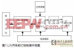
The LIN slave node processes the control signal sent by the master node and measures the state of the lamp driving circuit. After receiving the message information from the node, it sends corresponding control signals to the lights and analyzes the status of each light. If a failure occurs, a data message is generated and sent to the general node. After detecting the signal sent by the master node, the LIN slave node first recognizes it through the message frame to see if it belongs to its own message information. If it belongs, first judge whether the message is query information, if yes, return a response message, if it is control information, then control the corresponding lamp, and measure the potential of the measuring point on the lamp driving circuit and Be processed. See if it malfunctions. If a failure occurs, the information is sent to the general node through the LIN bus. And according to the sensor detects the light signal of the car ahead, make a judgment in real time, adjust the brightness and change of the light. Figure 1 shows the hardware block diagram of the LIN car headlight control.
MCU control unit
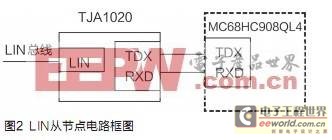
In the design, the MCU selects the MC68HC908QL4 of Freescale M68HC08 series as the MCU of the LIN slave node, and its circuit block diagram is shown in Figure 2. The 16-pin TOP packaged QL4 chip, VDD is connected to the + 5V power supply, and the SLCTX and SLCRX pins are connected to the TXD and RXD pins of the LIN transceiver (TJA1020), respectively. The LIN signal of + 12V comes in through the LIN pin of the transceiver, and the receiving and sending signals of + 5V are converted into the receiving and sending pins of QL4 by the transceiver.
After the initialization of the slave node is completed, other operations are completed in the interrupt. The SLIC state vector register (SLCSV) provides an index offset to directly reflect the current working state of the LIN module. It can be used to quickly enter an interrupt service subroutine together with the jump table provided by the user. All states of the LIN module have corresponding values ​​in the SLCSV. The value not only reflects the index offset of the LIN module state, but also reflects the priority of the interrupt.
LIN transceiver
This design selects TJAl020 as the LIN transceiver. TJAl020 is the interface between the LIN master / slave protocol controller and the LIN physical bus, which is mainly used as a vehicle auxiliary network. The baud rate is 2.4 ~ 20kbit / s. The transmission data stream input by the controller on the TXD pin is converted into a LIN bus signal by the LIN transceiver, and the conversion rate and waveform are controlled by the transceiver to reduce the extremely low electromagnetic emission (EME). The output pin of the LIN bus is pulled high by an internal termination resistor. The transceiver detects the data stream at the input pin of the LIN bus and sends it to the microcontroller via pin RXD.
Power module
In the design, the voltage regulators of the LIN module all use micro-power, low-dropout voltage regulator LTll2l-5. Select LTl121-5 to enter the stop mode by inputting low level to SHDN, at this time the quiescent current is only 16mA, so when there is no activity on the bus, the purpose of reducing power consumption can be achieved; in addition, the device The function of reverse input and output power can prevent reverse current flow even if no diode is added at the output end.
Driving circuit module of car lamp
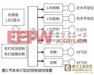
The designed lamp driving circuit module adopts distributed brake control, and its control box is shown in Figure 3. This control is used for horizontal positioning, rotation and AFS of dual headlights. The LIN micro-stepping motor driver is a two-phase driver with a positioning controller integrated with LIN control / diagnostics. This controller receives advanced positioning commands through the LIN interface and then drives the motor coil to the ideal position. The on-chip position controller can be configured for different motor types, positioning distances, and parameters (such as speed, acceleration, and deceleration). If the system detects a stall condition, sensorless stall detection will prevent the positioner from stepping out and stop the motor.
The high level of abstraction of the controller command set reduces the load on the microprocessor in the MCU. It is a straightforward method to apply adjustments according to the number of headlight motion control axes. Expanding the hardware and software design in a modular manner will not seriously affect the requirements for the main microcontroller. This system uses only one MCU, and it is very convenient to add or remove the optional motor when changing the system control function, and the cost is also very low. Current cars often include headlights with dynamic position control. For high intensity discharge (HID) xenon lamps, this function is critical. European safety regulations require that the vertical position of the main headlight beam can be dynamically controlled to avoid glare. If a stepper motor driver chip is used, an integrated electronic motor driver circuit can be designed for similar applications requiring only a few passive components for these applications.
The driver chip obtains high-level positioning control and diagnostic command instructions through a LIN, I2C or SPI bus, and converts it into a PWM signal that drives the coil of the stepper motor. The advantages of integrated motor driver circuits include increased system integration, reduced wiring harness complexity and reduced EMI radiation, which can reduce system cost, speed up time to market for end products and improve performance. Traditionally, automotive halogen headlight systems are equipped with a manual adjuster to align the vertical direction of the headlights. This device contains an analog servo system, including a transmission, brushed DC motor brake driven to a position corresponding to the manually adjusted position. The feedback of the servo system uses a potentiometer connected to the gear at the end of the brake, and the motor driver is a power amplifier. The system is relatively inexpensive.
This design uses the vertical positioning method of the linear stepper motor headlights. This type of motor is very reliable and does not require potentiometer feedback in open loop mode. Linear motion is achieved by a bolt / nut combination. The stepper motor rotating around the bolt has a control current in the stator coil to drive the magnetic rotor. Used for halogen headlight horizontal positioning system, vertical positioning, fully adaptive front lighting system (AFS), etc.
The car headlight is a device that is critical to the safety of the car at night. The motor that controls its position must also work in an automatic mode. If the communication bus fails, the light must be turned to a safe position. This requirement means that the driver circuit must detect the stall position without the aid of an external sensor, and through its micro-stepping mode, ensure that the movement is silent and smooth. Therefore, for any headlight position control architecture, whether centralized or distributed, these functions are very basic features.
software design
The lamp control system mainly completes two functions: one is to realize the control of the lamp by the LIN subnode; the other is to realize the diagnosis of the lamp failure. In control, determine whether the system is faulty by analyzing the bus potential and the potential of the input, output, and fault diagnosis pins in the drive circuit.
To enable LIN bus nodes to complete communication tasks effectively and in real time, software design is the key. This design uses a structured program design scheme, which has good modularity, portability and modifyability.
The reception of LIN information is interrupted. When the MC68HC908QL4 controller detects an information frame that meets the requirements of the node, it first judges what information the local node received. If it is control information, it receives 2 bytes of data information; if To query information, the status of the local node's car lights is sent back to the master node in the form of an information frame to reflect the status of the node. Then it is judged that if it is a received data frame, the corresponding information is read on the data register (SLCDx) in the SLIC module. Finally, the vehicle lights are controlled according to the relevant bits in the data information. After the control signal is issued, the potentials of the lamp drive chip input, output and fault diagnosis pins are collected accordingly to drive the movement of the lamp and turn on the horizontal direction lamp 1. Turn on the left and right direction lights and the AFS lighting system. Through the analysis of the potential, it sends a control signal to the drive circuit. If it is not necessary to start the lights, it sends a return message to return to the position of scanning the lights. The flow of its program design lamp control is shown in Figure 4.

After the system is started and initialized, the instrument module starts a timer to periodically scan the button status of the instrument lights on the instrument panel, and then transmits the information to the lamp control module through the LIN bus. This information includes the driver Requirements for the state of the lights (turning on or off). The car light control module simultaneously detects the car light information output by the digital diagnostic output and the car light output by the analog current sensor diagnostic output, and transmits the failed car light information to the instrument module through the LIN bus. The transmitted information includes the name of the lamp, the position of the lamp and the status of the lamp. The lamp control module combines the judgment result of the instrument module and the scan result of the instrument panel to decide whether to turn on the lamp or turn off the lamp. The instrument module receives / transmits the information of the lamp control module through the LIN bus.
Conclusion
Based on the LIN bus car headlight motion control system, it is possible to perform line diagnosis on the car lights through the LIN bus. The system has the characteristics of simple structure, reliable performance, uniform functions, and low price. For different stepper driver / controller combinations, The system design plan to realize the optimization of automobile headlight motion control system. The LIN node hardware structure of the MCU + LIN interface chip is designed, and the LIN network communication of the master / slave task is realized. At present, how to use bus technology to improve vehicle performance and reduce manufacturing and maintenance costs in China has become a hot spot for car manufacturers.
24 port PoE 10/100/1000M managed network switch/POE Switch/10/100/1000M 24 port POE
Managed POE Switch is designed for Video surveillance and network project system,etc.it provides 24x100Mbps Ethernet ports; 2x10/100/1000Mbps ports &2x1000 Base-X SFP optical fiber port as uplink ports; supports Web& CLI management,two layer network management and POE Intelligent management; supports data wire-speed and Jumbo Frame forwarding .Port based VLAN function can effectively prevent whole system from broadcast storm so that make the date transfer safer.The 16*10/100Mbps POE Switches complies with IEEE802.3 af/at standards,it simplifies wiring,avoids the troublesome of installing power socket for powered devices,such as
Features:
- Provide 24x 100Mbps ports; 2x10/100/1000 Mbps port & 2x1000 Base-X SF Poptical fiber port as uplink ports
- Support End-Span method,complies with IEEE802.3 af/at standards,flexibly configures power for each port.
- Support L2 switching function,including 802.1QVLAN,port mirroring, port isolation,IGMP Snooping function.
- LLDP,POE+Management and ARP detection.
- Support WEB,CLI,TELNET&SNMP management
- Support 10K Jambo Frames
- Support STP(802.1D) and RSTP(802.1W)
- Support IEEE802.3x full-duplex flow control,support Auto MDI/MDIX
- Restart funtion helps master IC reset wholly,Easy for users to solve network failure
- Without swapping power supply,easy to maintain system,help monitoring pictures ,recover quickly.
- Excellent lighting protection,lightning capacity up to 2KV.
Application:
- Security Monitoring system
- Multimedia Network Teaching System
- Medical Monitoring Display System
- Industrial Automation Control System
- Banking ,securities,financial information display system
- Remote Network Server Monitoring
- Department Store Security
- Casino Security
- Hospitals,Airports and banks
- School Campuses
Gigabit Standard Managed Poe Switch
Gigabit Standard Managed Poe Switch,8 Port Poe Switch,250M Poe Transmission,Giga Managed Power
Guangdong Steady Technology Co.LTD , https://www.steadysmps.com