Numerical analysis of Rotman lens multi-beam forming network
In this paper, an important multi-beam forming network-Rotman lens is analyzed by combining the slab waveguide model method and the contour integral equation method. First, the equivalent slab waveguide model of the lens considering the dispersion effect is established, and then the appropriate waveguide mode function is selected to expand the lens The field on the port, and use the Galerkin method to solve the contour integral equation that the electric field on the edge meets to obtain the multi-mode scattering parameters of the lens. Then according to the network idea, the high-order modes existing at the port are used as loading. Thus the scattering parameters of the main mode excitation are obtained , The calculated results agree well with the experimental results.
Keywords: multi-beam network; Rotman lens, planar waveguide model method; profile integral equation method
Numerical Analysis of Rotman Lens-type MulTIple Beamforming Networks
YUAN Ning, LIANG Chang-hong, ZHENG Jia-jun
(Dept. of Microwave TelecommunicaTIons Engineering, Xidian University, Xi'an 710071, China)
Abstract: The analysis of Rotman lens, an important mulTIple beamforming network is accomplished by the contour integral equaTIon method along with the planar waveguide model method. First, the planar waveguide models for Rotman lens and its feed lines which incorporate the dispersion effect with frequencies are set up.Then the aperture electric fields at lens ports are expanded by appropriate waveguide mode functions and substituted into the contour integral equation.The multimode scattering matrix of the lens can be acquired by solving the contour integral equation by using Galerkin method.To obtain the scattering matrix corresponding to the dominant mode, higher order modes aroused at lens ports are treated as loads of the network. It is proved that the calculated results are in good agreement with the experimental ones.
Key words: multiple beam forming network; Rotman lens; planar waveguide model method; contour integral equation method
1. Introduction The Rotman lens is an effective means of generating a multi-beam system. In recent years, it has been more and more widely used in electronic warfare, early warning systems and personal communication systems. Compared with other multi-beam feeding systems, it has Some significant advantages [1]: (1) Because it is based on the principle of equal optical path, the beam pointing does not change with frequency; (2) each beam has a full aperture gain; (3) is often implemented in the form of microstrip, so The circuit is simple, small in size and light in weight; (4) has good broadband performance and can reach octave bandwidth.
When the parameters are given, the input and output profiles of the Rotman lens can be determined by the geometric optical design formula [1]. However, the virtual port profile, which has an important influence on the lens performance, is not constrained by the design equation and is the degree of freedom of design. To optimize the design of the virtual port, we must understand the field distribution at the edge of the lens. This article combines the planar waveguide model method and the contour integral equation method to analyze the Rotman lens strictly. Because the Rotman lens often works at a higher frequency ( Several GHz to dozens of GHz) and a wider frequency band, so when establishing its equivalent slab waveguide model, the dispersion effect of equivalent parameters on frequency is considered, so that the influence of higher-order modes is taken into account and can be reflected more accurately Actual situation. After obtaining the equivalent slab waveguide model of the lens and the connected feeder, according to the characteristics of the internal field of the lens, the electric field is expanded using the appropriate waveguide mode function at its port, and the contour integration equation satisfied by the field is substituted by Galerkin. Method to solve these expansion coefficients, you can get the multi-mode scattering parameters of the lens. Generally, the lens port is connected by a gradient line to only transmit The feed line of the mode, so this paper regards the high-order mode caused by port non-uniformity as the loading of the network, so as to obtain the scattering parameters of the lens excited by the TEM mode. The method of this paper considers the influence of the high-order mode, the multiple reflection effect between the contours and each The coupling between the ports can reflect the lens performance more accurately, and the convergence of this method is very good, only the first few expansion modes are needed, so the calculation amount is small and the speed is fast, which is very suitable for Rotman with large electrical size Numerical analysis of the lens.
Second, the establishment of the equivalent slab waveguide model Figure 1 shows a cross-sectional view of a microstrip line and its equivalent slab waveguide model. In the waveguide model of Figure 1 (b), the upper and lower ends are electrical walls, left, The right end is the magnetic wall, which is filled with a medium with a dielectric constant of εe (f), and the height h of the model is equal to the thickness of the microstrip dielectric substrate.
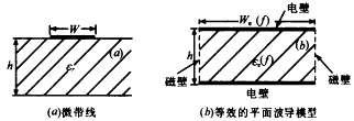
Figure 1 Microstrip line and its equivalent slab waveguide model In order for this equivalent model to reflect the effects of higher-order modes, it is applicable in the entire frequency band, we consider the dispersion effect of equivalent parameters, and the dynamic equivalent dielectric constant εe (f) and equivalent width we (f) vary with frequency The relationship is [2]:
Where εeff and weff are the static equivalent dielectric constant and equivalent width, respectively, and fT is the cutoff frequency of the lowest order mode, defined as:
Where c is the speed of light in free space, and Δw represents the fringe field effect at the edge of the microstrip. For different aspect ratios w / h, the expressions of Z0 and εeff are also different. This paper uses Gupta's empirical formula [3] to calculate Z0, εeff and Δw. The static equivalent width weff can be determined by the following formula:
After calculating fT, εeff and weff, εe (f) and we (f) at different frequencies can be obtained according to equations (1) and (2), thus the microstrip line can be equivalent to the corresponding planar waveguide Model. For the microstrip Rotman lens shown in Figure 2, the equivalent slab waveguide model should be the similar shape of the original lens. When the shape of the lens is determined, the width of all its ports can be known, using the aforementioned method can be obtained The equivalent width of each port, and then use these equivalent port widths as constraints, and keep the center of the lens unchanged and each section of the equivalent profile is parallel to the corresponding section of the original lens. Find the similar shape of the original lens. Obtain the outline of the equivalent slab waveguide model that satisfies the above frequency dispersion effect. The following analysis is carried out for this equivalent model. |
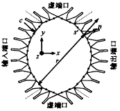
Figure 2 Rotman lens schematic 3. Multi-mode scattering parameters and processing of high-order modes are shown in Figure 2. The outline of the Rotman lens is composed of three parts: input port (beam port), output port (array port) and virtual port. Since the thickness of the medium is very small, it can be It is approximated that the field in the z direction perpendicular to the surface of the conductor does not change, so only the three components of Ez, Hx and Hy are not zero. The electric field distribution derived from the two-dimensional Hemholtz equation at the edge of the lens cavity can be described by the following contour integral equation [ 4, 5]:
Where H (2) 0 and H (2) 1 represent the second-order zero-order and first-order Hankel functions, s and s ′ denote the field point and source point on the contour c, respectively, r = r
Because only the three components of Ez, Hx, and Hy are not zero in the lens cavity, only TEp0 (p = 0,1,2, ...) modes exist in the planar waveguide connected to them, which are expressed by these orthogonal mode functions Field distribution on the port (ie M patterns):
Where Akp and Bkp represent the p-order modes incident and reflected at the k-th port, respectively, Ykp and γkp are their mode admittance and propagation constant, wk is the width of the k-th port, and εp is the Newman constant, when p = 0 (corresponding to TEM mode), εp = 1, p ≠0, εp = 2. Using the local coordinate system to analyze each port, the following equation can be obtained from equation (7):
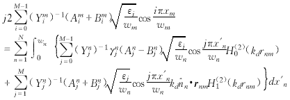
Write the expansion of Ez (sm) and Ez (s′n) according to equation (7), and substitute equation (8) into equation (6) to get:
Using Galerkin method, weight function
among them:
When m ≠n, that is, the field point and the source point are in different regions, the double integral of the above two equations can be conveniently obtained by numerical integration method, when m = n, that is, the field point and the source point are located in the same region, Gmnij = 0 , And Fmnij appears singularity, which can be solved by variable substitution combined with singular point removal method [6]. CB = DA (13) The elements of matrix C and D are: Ckl = (Ynj) -1 (γnjFmnij-kdGmnij), A and B respectively represent the following column vectors: A = [A10A20 ... AN0 A11 ... AN1 ... A1M-1 ... ANM-1] T (16) Where Akp and Bkp represent the incident and reflected waves of the p-th mode of the k-th port, respectively. Solving the matrix equation of (13) gives the multi-mode scattering matrix of the Rotman lens: S = C-1D (18) Normally, the lens port is connected to the transmission line that only transmits the main mode through the gradient line. The energy of the higher-order mode excited by the port is continuously reflected back to the lens cavity within the gradient line, and finally only the main mode propagates. We put these withered higher-order modes It is regarded as the loading of the multi-port network of lenses. The characteristic impedance Zm0i of the i-th mode of the m-th port can be calculated by the following formula [7]:
Then the load reflection coefficient corresponding to the i-th mode of the m-th port is: Γ (i-1) N + m = (Zm0i-Zm0) / (Zm0i + Zm0) (20) Where Zm0 is the characteristic impedance of the equivalent planar waveguide of the corresponding port. Set in all N × M ports, the 1st to Nth ports corresponding to the main mode are zone I, and the remaining (M-1) × N higher order modes The corresponding port N + 1 ~ N × M is the second zone, then the single-mode scattering matrix [Sm] of the lens loaded by the higher-order mode is excited by the main mode. Out [8]: [Sm] = [Sâ…¡] + [Sâ… â…¡] {[Γ] -1- [Sâ…¡ â…¡]}-1 [Sâ…¡ â… ] (21) Where [Γ] is a diagonal matrix composed of the load reflection coefficients of high-order mode ports N + 1 ~ N × M. 4. Calculation example and discussion Using the above method, the 32 × 32 yuan Rotman lens shown in Figure 3 is calculated and compared with the experimental results. It has 32 input ports, 32 output ports, and 16 virtual load ports. Angle α = 35 °, scanning angle β = 45 °, dielectric constant εr = 2.2, substrate thickness d = 1mm. Because there are many lens ports, we only use the most representative edge beam opening 1 and center beam opening 16 As an example, the lens is given the amplitude and phase distribution of the output port when the two ports are excited at an intermediate frequency f = 12GHz. These calculation results are obtained by taking four expansion mode functions. |
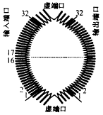
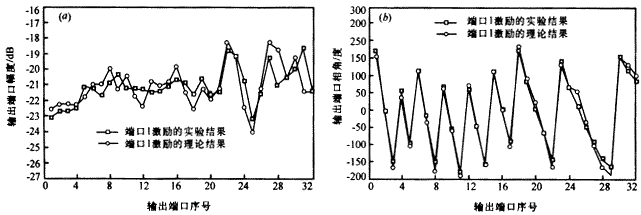
Figure 3 32 × 32 yuan Rotman lens used in calculation and experiment The box line in Figure 4 (a) represents the amplitude distribution of the output port measured by the experiment when the beam port 1 is excited. The circle line is the theoretical calculation result, and Figure 4 (b) is the corresponding phase distribution. Figure 5 (a) and 5 (b) is the amplitude and phase distribution of the output port when the central beam port 16 is excited. It can be seen from the figure that the amplitude fluctuation of the edge port is relatively large, and the amplitude of the center port is relatively stable, regardless of the edge port or the center port, The experimental results and the calculation results are in good agreement. Except for individual points, the amplitude error is usually about 0.5dB, and the phase error is generally below ten degrees. The selection is more appropriate, so although there are many input ports, the coupling between them is small and the isolation is good. The isolation between the beam ports 1 and 16 and other beam ports given in Table 1 can be seen a little.
Figure 4 (a) Amplitude distribution of output port when input port 1 is excited; (b) Phase distribution of output port when input port 1 is excited |

Figure 5 (a) Amplitude distribution of output port when input port 16 is excited; (b) Phase distribution of output port when input port 16 is excited Table 1 Isolation between input ports |
| Beam number | 1-2 | 1-4 | 1-8 | 1-12 | 1-16 | 1-20 | 1-24 | 1-28 | 1-32 |
| Isolation (dB) | -17.78 | -24.89 | -26.93 | -45.81 | -24.88 | -27.26 | -31.83 | -26.08 | -29.32 |
| Beam number | 16-1 | 16-4 | 16-8 | 16-12 | 16-17 | 16-20 | 16-24 | 16-28 | 16-32 |
| Isolation (dB) | -25.73 | -26.54 | -27.45 | -23.5 | -13.01 | -24.21 | -28.82 | -26.1 | -31.14 |
| V. Conclusion In this paper, the planar waveguide model with dispersion effect of the Rotman lens is first established, and then the required electric field is expanded using the waveguide mode function, and the performance analysis of the Rotman lens is completed in conjunction with the contour integral equation method. Because the method has good convergence Only the first few expansion modes are needed, so the method in this paper has a smaller calculation amount and faster calculation speed than the boundary element method, and due to the influence of higher-order modes, it can reflect the actual situation more. The calculated results are in good agreement with the experiment .Using the method in this paper, it is convenient to investigate the influence of lens parameters and virtual port profile on its performance, and realize the optimized design of lens profile. |
The PufangTech SCADA wireless modems are designed to meet the requirement of wireless SCADA systems. It provides a cost effective solution for remote supervision and control and is suitable for almost anything such as machines, devices, processes, pipelines, tanks, street lights, pumps, valves, unmanned stations etc. If you have many targets while cable is not a practical solution and you want to have a way to monitor and control them, then PufangTech`s SCADA wireless modem is most likely what you are searching for.
The PufangTech wireless modems can be used for simplex or semi-duplex operation with up to 60 discrete channels.
The transmit power can be set using a locally connected PC with the supplied Windows based configuration software. There are usually five output power levels available which can be selected from.
SCADA Wireless Modem,SCADA Wireless Modem Router,Wireless Edge Modem Router,Wireless Internet Modem
Shenzhen PuFang Technology Co., Ltd. , https://www.hytelus.com

 (6)
(6)  (8)
(8)  (9)
(9)  (10)
(10)  (12)
(12) 