
This article presents the design of two stepping motor control systems based on the 89C51 single-chip microcontroller. It provides a detailed explanation of the system architecture, power supply section, button interface, driving circuit, and status indication module.
Design of Stepping Motor Control System for 89C51 Single-Chip MicrocomputerFigure 1 shows the overall system diagram. The system operates in external interrupt mode, where the P0 port is used as the input interface, the P1 port controls the LED display, and the P2 port drives the stepper motor. This configuration allows for efficient signal processing and motor control using the 89C51 microcontroller.
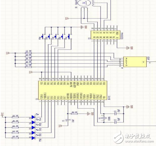
Figure 1: System Diagram
Power Supply SectionThe power supply section utilizes LM7812 and LM7805 voltage regulators to provide 12V and 5V outputs, respectively. These components are essential for powering the stepper motor and the microcontroller. Key considerations include:
The input and output voltage difference should not be too large, as excessive voltage can reduce efficiency and potentially damage the ICs.
The output current must not exceed 1.5A. High current operation requires adequate heat dissipation to avoid overheating and thermal shutdown.
Maintaining an appropriate voltage difference is crucial for optimal performance. A very small difference may result in poor regulation and inefficiency.
The 12V supply powers the motor, while the 5V supplies the microcontroller. Figures 2 and 3 illustrate the respective circuits.
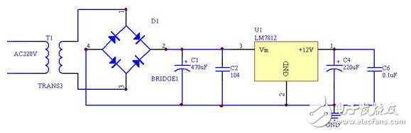
Figure 2: 12V Power Circuit
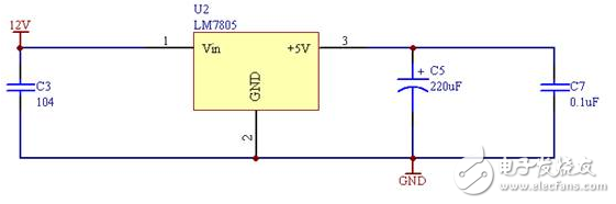
Figure 3: 5V Power Circuit
Button InterfaceThe P0 port of the microcontroller is used to detect button presses. Each button connects to a specific pin on the P0 port. When pressed, it pulls the corresponding pin low, signaling the microcontroller to execute the associated function. For example:
Pressing S1 sets P0.0 to low.
Pressing S2 sets P0.1 to low.
And so on for S3, S4, and S5.
This setup enables user interaction with the system. Figure 4 shows the button interface circuit.
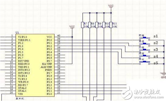
Figure 4: Button Interface Circuit
Motor Drive SectionThe drive circuit uses the ULN2004 chip, which contains seven NPN Darlington transistors. This driver is ideal for controlling high-current loads such as stepper motors. It acts as an interface between the microcontroller and the motor, ensuring safe and efficient operation. Figure 5 illustrates the drive circuit.
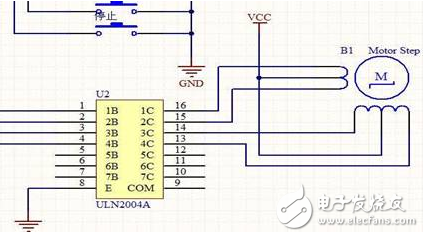
Figure 5: Motor Drive Circuit
Status Indication SectionThe P1 port is used to control an LED display that indicates the motor’s status. When a specific port pin is set low, the corresponding LED lights up, providing visual feedback about the motor's operation.
Clock CircuitThe clock circuit is a critical component of the microcontroller system, determining the timing and speed of operations. In this design, a 12MHz crystal oscillator is used to ensure stable and precise timing. The clock circuit is shown in Figure 6.
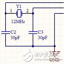
Figure 6: Clock Circuit
Wire Feeding Machine,Wire Feeder Mechanism,Tube Crimping Machine,Cable Stripping Machine
Kunshan Bolun Automation Equipment Co., Ltd , https://www.bolunmachinery.com