
This article presents the design of two stepping motor control systems based on the 89C51 single-chip microcontroller. The system is designed to provide precise control over the movement of a stepper motor, making it suitable for applications such as robotics, automation, and precision positioning systems.
System OverviewThe overall system architecture is illustrated in Figure 1. The system operates using an external interrupt mode, allowing the microcontroller to respond to input signals efficiently. The P0 port serves as the input interface for user commands, while the P1 port is connected to an LED display for status indication. The P2 port is responsible for driving the stepper motor, providing the necessary signals to control its rotation.
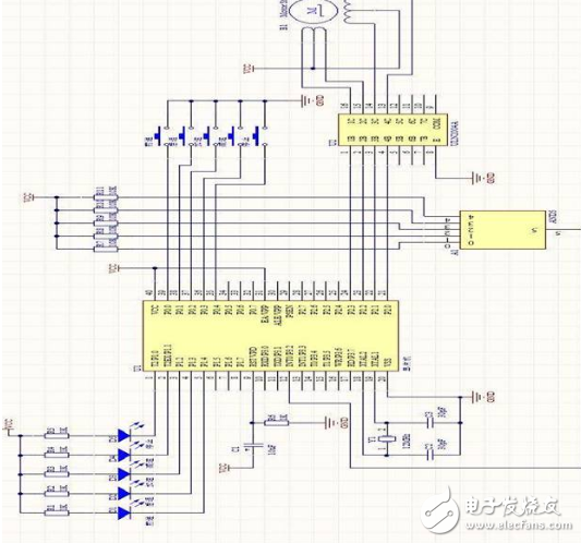
Figure 1: System Block Diagram
Power Supply SectionTo power the system, the LM7812 and LM7805 voltage regulators are used to generate 12V and 5V outputs, respectively. These components are essential for supplying stable power to both the motor and the microcontroller. Key considerations when using these regulators include:
The input-to-output voltage difference should not be too large, as excessive voltage can reduce efficiency and potentially damage the regulator.
The output current must remain within safe limits—1.5A is the maximum rating. Exceeding this can cause overheating, leading to thermal shutdown or failure.
The voltage difference should also not be too small, as this reduces efficiency. The 12V supply powers the stepper motor, while the 5V supply powers the microcontroller.
Figure 2 shows the 12V power circuit, and Figure 3 illustrates the 5V power circuit.
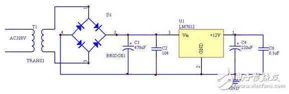
Figure 2: 12V Power Circuit
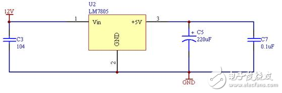
Figure 3: 5V Power Circuit
Button Input SectionThe system uses the P0 port of the 89C51 microcontroller to receive input signals from buttons. Each button corresponds to a specific pin on the P0 port. For example, pressing switch S1 sets P0.0 to a low level, S2 sets P0.1, and so on up to S5, which affects P0.4. These inputs are then processed by the microcontroller to perform the desired operations.
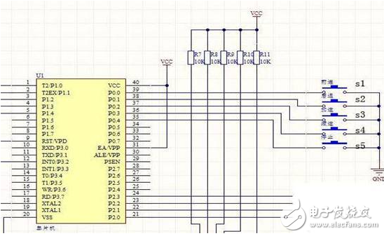
Figure 4: Button Input Circuit
Motor Drive SectionThe drive section of the system uses the ULN2004 chip, which is a high-voltage, high-current Darlington transistor array. This chip is ideal for driving stepper motors, as it can handle the higher currents required without damaging the microcontroller. The ULN2004 contains seven NPN Darlington pairs, making it well-suited for controlling multiple motor phases.
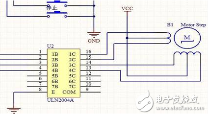
Figure 5: Motor Drive Circuit
Status IndicationThe status of the system is indicated through LEDs connected to the P1 port of the microcontroller. When a particular port is set to a low level, the corresponding LED lights up, providing visual feedback on the motor's state.
Clock CircuitThe clock circuit is crucial for the operation of the microcontroller. It determines the timing and speed of the CPU. In this design, a 12MHz crystal oscillator is used to ensure accurate and stable operation. The clock circuit is shown in Figure 6.
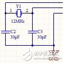
Figure 6: Clock Circuit
New Energy Cable Processing,Wire Stripping Machine,Electric Wire Cutter,Electric Wire Stripper
Kunshan Bolun Automation Equipment Co., Ltd , https://www.bolunmachinery.com