
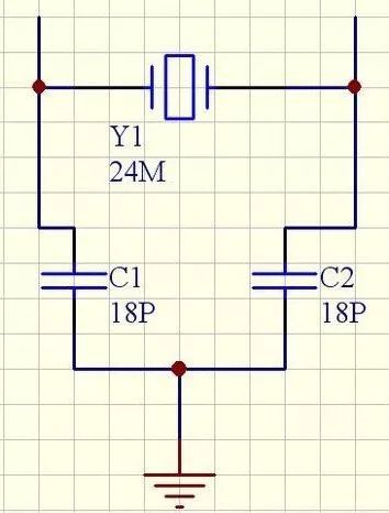
When it comes to the calculation of crystal load capacitance, it's a critical factor in ensuring the proper operation of oscillators in electronic circuits. The two capacitors labeled C1 and C2 in the diagram are referred to as the load capacitance of the crystal oscillator. These capacitors are connected between the two pins of the crystal and ground. Their values typically range from a few picofarads up to about 30 pF, and they play a key role in determining both the resonant frequency and output amplitude of the oscillator. When ordering a crystal, manufacturers often ask for the load capacitance value to ensure compatibility with your design.
The formula for calculating the crystal load capacitance is: Crystal Load Capacitance = (C1 × C2) / (C1 + C2) + Cic + ΔC. Here, C1 and C2 are the external capacitors connected to each leg of the crystal and to ground. The term "Cic" represents the internal capacitance of the integrated circuit, while ΔC accounts for the parasitic capacitance on the PCB. For example, if a crystal specifies a 12 pF load capacitance, you might use 22 pF capacitors on each side, accounting for an additional 2 pF of parasitic capacitance on each pin.
In practical terms, this means that if the desired load capacitance is 15 pF, the two external capacitors should be around 27 pF each. This ensures that the equivalent capacitance seen by the crystal matches the required load value.
Many logic chips implement a three-point capacitor oscillator configuration at the crystal input and output pins. Inside the chip, these pins usually contain an inverter or a series of inverters. A resistor is often placed between the output (XO) and input (XI) of the crystal oscillator. For CMOS devices, this resistor can range from several megaohms to tens of megaohms. Some chips already include this resistor internally, so no external component is needed. The purpose of this resistor is to bias the inverter into a linear region, allowing it to function as an amplifier during startup.
The quartz crystal itself is connected between the input and output of the oscillator pin, forming a parallel resonant circuit. The two capacitors connected to ground act as a voltage divider, creating a feedback path that sustains oscillation. If the two capacitors are equal, the feedback coefficient is 0.5, which generally meets the oscillation condition. However, if the circuit is unstable or doesn’t start easily, adjusting the capacitance—by reducing the input-side capacitor and increasing the output-side one—can help improve feedback and stability.
To summarize, here are a few important points to keep in mind:
Matching capacitors are used to adjust the effective capacitance across the crystal to match the specified load capacitance. In many cases, the external capacitors are set to twice the required load capacitance, which helps achieve a closer match.
Load capacitance refers to the total external capacitance seen across the crystal in the circuit. It’s a test and operational parameter. When designing, it's often fine-tuned to achieve a precise frequency close to the specified value.
Increasing the load capacitance tends to lower the oscillation frequency, while decreasing it raises the frequency.
Load capacitance includes all internal and external capacitances connected to the crystal’s two leads. It acts like a series capacitor in the resonant circuit. Different load capacitances result in different oscillation frequencies. Even crystals with the same nominal frequency may have different load requirements because they can resonate in either series or parallel mode. Therefore, swapping crystals without matching the load capacitance can cause malfunctions in the circuit.
16MM Metal Switches
Yeswitch 16MM Metal Switches could be divided into aluminum casing and stainless steel casing and also could be divided into Momentary Switch and self-locking Metal Push Button Switch .
This 16MM series Waterproof Push Button Switch offer a long life expectancy, could used in Industrial control instruments, Medical equipment, Security monitoring equipment, Vehicle peripherals, Audio-visual equipment and Energy storage equipment,etc.

In addition, All casings are made through high-precision lathes, and the polishing and plating are rigorously screened. The metal fittings inside the metal switches are made of brass gold plated material, so the switch can have good conduction function and stable quality after long-term use.
The 16 series illuminated metal switches offer a long life expectancy, water resistance to IP67 ratings, and ring or power symbol illumination.This switch has a 16mm panel cutout size. Additional options include a high, high flat or rounded bezel option, and your choice of a solder lug or wire lead termination.
As for the indicator light , we offer customized service, customers could choose the effect , shape and the color. What is worth mentioning is that our indicator light could offer double color, which could offer our customers more choose in the item of light. Meanwhile, on the item of terminal shape, we could also offer customized service, we have solder terminal and free wire length could choose, 500mm is the normal standard.

This serious metal push button switches are of high quality and reliable products. The switch has passed IP67 dust proof and waterproof certification, which indicates it can be operated in harsh environments. Moreover, all materials could meet the European and American environmental protection requirements , for example, UL and ROHS certificate.
16mm Metal Switch,16mm Metal Push Button Switches,16mm Waterproof Metal Switch,16mm Waterproof Metal Push Button Switch Switch,16mm Momentary Metal Switch,16mm Metal Push Button Switch
YESWITCH ELECTRONICS CO., LTD. , https://www.yeswitches.com