
Hall Sensor is a magnetic field sensor based on Hall effect, which is widely used in industrial automation technology, detection technology and information processing. So what is the working principle of the Hall sensor? What are the advantages of this type of sensor? What are the main parameters? This article will answer one by one.
(The essence of the Hall effect is that when carriers in a solid material move in an applied magnetic field, the trajectory shifts due to the Lorentz force, and charge accumulation occurs on both sides of the material, forming a perpendicular to the current. The electric field in the direction eventually balances the Lorentz force of the carrier with the repulsion of the electric field, thereby establishing a stable potential difference, that is, the Hall voltage on both sides.)
The Hall coefficient measured by the Hall effect experiment can determine important parameters such as conductivity type, carrier concentration, and carrier mobility of the semiconductor material.
Since the potential difference generated by the Hall element is small, the Hall element is usually integrated with an amplifier circuit, a temperature compensation circuit, and a regulated power supply circuit on a chip, which is called a Hall sensor. Hall sensors, also known as Hall ICs, have a small profile, as shown in the following figure:
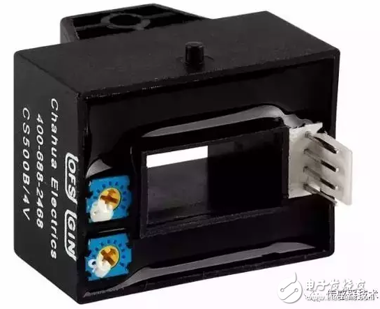
Hall sensor
Advantages and uses of Hall sensorsMany people know that the more automated the car, the more microelectronic circuits, the more afraid of electromagnetic interference. In the car, there are many lamps and electrical devices, especially the high-power headlamps, air-conditioner motors and wiper motors generate surge current when switching, causing arcing of mechanical switch contacts and generating large electromagnetic interference. signal.
These phenomena can be reduced by using a power Hall switching circuit. The Hall device is converted to an electrical signal output by detecting changes in the magnetic field and can be used to monitor and measure changes in the operating parameters of various components of the vehicle.
Such as position, displacement, angle, angular velocity, rotational speed, etc., and these variables can be transformed twice; pressure, mass, liquid level, flow rate, flow rate, etc. can be measured. The output of the Hall device is directly interfaced with the electronic control unit for automatic detection.
The current Hall devices can withstand certain vibrations, and can work in the range of minus 40 ° C to minus 150 ° C. All the seals are not polluted by water and oil, and can fully adapt to the harsh working environment of the car.
Hall sensors measure current and voltage in arbitrary waveforms such as DC, AC, pulse waveforms, and even transient peak measurements. The secondary current faithfully reflects the waveform of the primary current. Or ordinary transformers can not be compared with it, it is generally only suitable for measuring 50Hz sine wave
There is good electrical isolation between the primary side circuit and the secondary side circuit, and the isolation voltage can reach 9600Vrms;
High precision: accuracy is better than 1% in the working temperature zone. This precision is suitable for any waveform measurement; Hall switch device has no contact, no wear, clear output waveform, no jitter, no rebound, high position repeatability ( Up to μm level).
Wide bandwidth: The high-bandwidth current sensor rise time can be less than 1μs; however, the voltage sensor bandwidth is narrow, generally within 15kHz, and the 6400Vrms high-voltage voltage sensor has a rise time of about 500uS and a bandwidth of about 700Hz.
Wide measurement range: current measurement up to 50KA, voltage measurement up to 6400V.
The structure is firm, the volume is small, the weight is light, the service life is long, the installation is convenient, the power consumption is small, the frequency is high (up to 1 MHZ), the vibration is resistant, and the pollution or corrosion of dust, oil, water vapor and salt spray is not afraid.
The picture above shows a typical Hall sensor for positioning applications - two magnets on one wheel pass through a Hall effect sensor. The wheel in the illustration, with two equidistant magnets, the voltage across the sensor will peak twice in one cycle.
It is commonly used to measure the speed of wheels and shafts, such as at the ignition timing (timing) of an internal combustion engine or on a tachometer. It is used in brushless DC motors to detect the position of permanent magnets.
Hall sensors are widely used in frequency conversion speed control devices, inverter devices, UPS power supplies, communication power supplies, electric welding machines, electric locomotives, substations, CNC machine tools, electrolytic plating, computer monitoring, power grid monitoring, etc. Solar, wind and subway track signals, automotive electronics and other fields.
Main characteristic parameters of Hall sensorAs mentioned above, the Hall sensor is a magnetic field sensor fabricated according to the Hall effect. Its main characteristic parameters are as follows.
(1) Input resistance R
The DC resistance of the two excitation current terminals of the Hall sensor element is called an input resistance. Its value ranges from a few euros to a hundred euros, depending on the components of the different models.
As the temperature rises, the input resistance becomes smaller, which causes the input current to become larger, eventually causing the Hall sensor potential to change. In order to reduce this effect, it is preferable to use a constant current source as an excitation source.
(2) Output resistance R
The resistance between the potential outputs of the two Hall sensors is called the output resistance, and its digits are of the same order of magnitude as the input resistance. It also changes with temperature changes. Choosing the appropriate load resistor is easy to match to minimize the drift of the temperature-induced water potential.
(3) Maximum excitation current I---Hall sensor parameters
Since the potential of the Hall sensor increases with the increase of the excitation current, it is always desirable to select a larger excitation current of 1 M in the application but the excitation current is increased, the power consumption of the component is increased, and the temperature of the component is increased. As a result, the temperature drift of the Hall sensor's potential increases, so each of the models specifies a corresponding maximum excitation current, which ranges from a few milliamps to hundreds of milliamps.
(4) Sensitivity K
Sensitivity KH = EH / IB, its value is about 10MV (MA.T).
(5) Maximum magnetic induction BM---Hall sensor parameters
When the magnetic induction exceeds BM, the nonlinear error of the Hall sensor potential will increase significantly, and Tes(T) becomes several thousand Gauss (Gs) (1Gs = 104T).
(6) an equipotential potential
At the rated excitation current F, when the applied magnetic field is zero, it is an error due to the asymmetry of the geometry of the four dipoles.
(7) Hall sensor potential temperature coefficient
The value of 6M is generally zero. The open circuit voltage between the output terminals of the Hall sensor is called the unequal potential. When using the bridge method, the bridge method is used to compensate the unequal potential, which is caused by a certain magnetic induction intensity and excitation current. When the temperature changes by 1 degree Celsius, the percentage change of the Hall sensor potential is weakly the Hall sensor potential temperature coefficient, which is related to the material of the Hall sensor element.
Resolver is a kind of commonly used angle detection component, because of its simple structure, reliable operation, and its accuracy can meet the general detection requirements

Resolver,Encoder Troubleshooting Resolver,Custom Resolver,Online Resolver
Yuheng Optics Co., Ltd.(Changchun) , https://www.yhencoder.com